
Creep in PTFE sheets is the slow, permanent deformation that continues under a constant load, even at room temperature. Unlike metals, PTFE (polytetrafluoroethylene) deforms continuously because its crystalline structure slips under stress. A sheet compressed at 10 MPa can lose 5–15% of its thickness within 1,000 hours at 23°C, and more as temperature rises. This article explains the mechanism, gives you a step-by-step method to predict and control creep, and shows the exact mistakes that cause seal and gasket failures. After reading, you will be able to estimate long-term thickness loss for a PTFE sheet and decide whether it fits your application.
Table of Contents
1. Why PTFE Creeps: The Mechanism
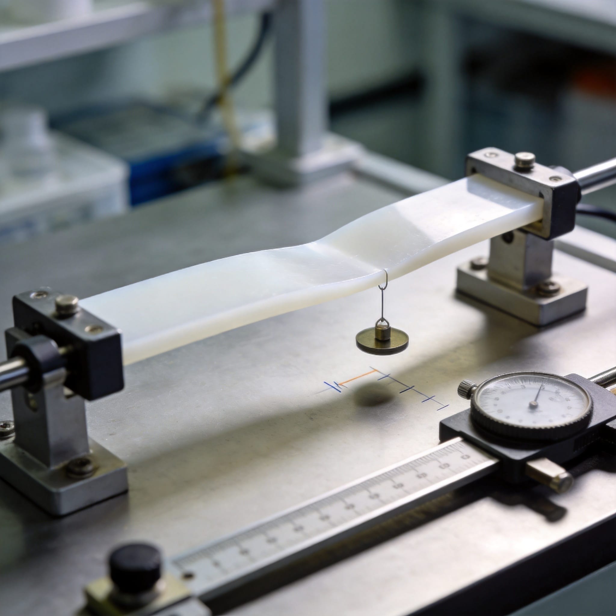
PTFE is a semi-crystalline polymer. Its long chains slide past each other when stress is applied, and the crystalline regions gradually reorganize. This is why PTFE has a compressive creep rate roughly 10 to 100 times higher than filled grades or other engineering plastics such as POM or PEEK.
Three variables control creep: stress, temperature, and time. Temperature matters most. Raising the temperature from 23°C to 100°C can increase creep by a factor of 5–10. Filler content matters too: adding 25% glass fiber or carbon reduces creep by 40–60% compared to virgin PTFE skived sheet.
| Stress (MPa) | 100 h | 1,000 h | 10,000 h |
|---|---|---|---|
| 5 | 1.5% | 2.8% | 4.5% |
| 10 | 3.2% | 6.0% | 9.5% |
| 20 | 7.0% | 12.5% | 18.0% |
These values follow a power law: strain at time t equals strain at 1 hour multiplied by tn, where n is about 0.1–0.2 for PTFE. That means most creep happens early and then slows, but it never stops. For authoritative property data, see the NIST materials database and the ASTM D2990 standard for tensile and compressive creep testing.
2. How to Predict and Control Creep: Step-by-Step
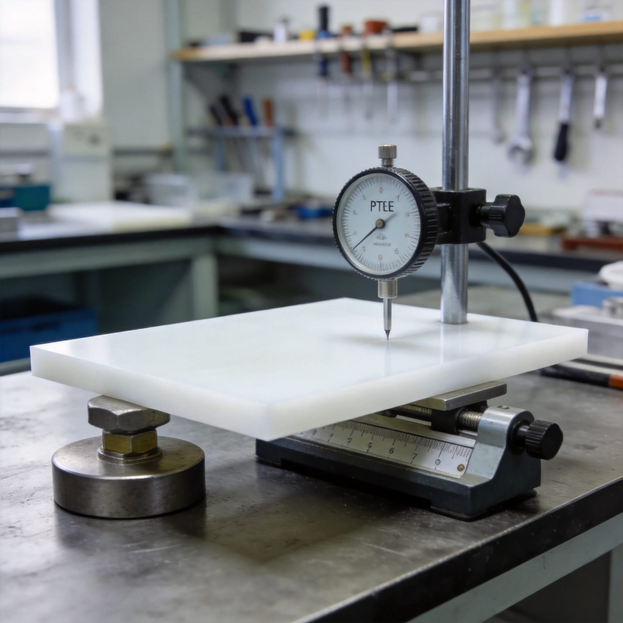
Follow these steps to estimate long-term thickness loss and choose a design that stays stable.
- Define your service conditions. Write down the compressive stress (MPa), the maximum continuous temperature (°C), and the required service life (hours). Example: 8 MPa, 60°C, 20,000 hours.
- Find the base creep strain at 23°C. Use a creep table like the one above, or the manufacturer’s ISO 899-1 data. At 8 MPa and 1,000 hours, interpolate between 6.0% and 12.5% to get about 7.5%.
- Apply the temperature correction factor. Multiply by the factor from your supplier’s curve. At 60°C the factor is typically 2.0–2.5. So 7.5% × 2.2 = 16.5%.
- Extrapolate to your service life. Use the power law: strain at 20,000 h = strain at 1,000 h × (20,000/1,000)0.15 = 16.5% × 1.57 = 25.9%.
- Compare to your allowable limit. If your seal can tolerate only 15% thickness loss, this design fails. Reduce stress to 4 MPa or switch to a 25% glass-filled PTFE sheet.
- Verify with a test coupon. Compress a 25 mm × 25 mm sample under the same load and temperature for 500 hours. Measure thickness with a micrometer every 100 hours. Compare to your prediction; adjust the factor if the deviation exceeds 15%.
- Set a re-torque interval. If you must use virgin PTFE, schedule bolt re-torquing every 2,000–3,000 hours to recover lost compression.
Decision rule: If predicted creep strain exceeds 10% of sheet thickness over the service life, use a filled grade or a different material. Do not rely on virgin PTFE for structural compression above 7 MPa at elevated temperature.
3. Common Mistakes and Fixes
These errors appear repeatedly in field failures. Each has a symptom and a concrete fix.
- Mistake 1: Using room-temperature data for a hot application.
Symptom: The joint leaks after 3–6 months at 80°C even though calculations at 23°C passed.
Fix: Always multiply creep strain by the temperature factor. At 80°C, use a factor of 3.0 minimum for virgin PTFE. - Mistake 2: Ignoring the difference between virgin and filled PTFE.
Symptom: A glass-filled sheet performs well, so you switch to virgin PTFE to save cost, and the seal fails.
Fix: Keep a material substitution log. A glass-microbead-filled PTFE sheet has 40–60% less creep. Never substitute without recalculating. - Mistake 3: Assuming creep stops after the break-in period.
Symptom: Thickness looks stable at 500 hours, so you stop monitoring. At 5,000 hours the seal has lost 20% thickness.
Fix: Monitor for the full service life. PTFE creep follows a power law and continues indefinitely. Set a mid-life inspection at 50% of expected service hours. - Mistake 4: Over-torquing bolts to “compensate” for creep.
Symptom: The sheet cold-flows out of the joint, causing extrusion and a new leak path.
Fix: Torque to the manufacturer’s specification and re-torque at intervals instead of over-compressing at installation.
4. FAQ
Q1: Does PTFE creep at room temperature?
Yes. At 23°C and 10 MPa, virgin PTFE creeps about 6% in 1,000 hours. It is slower than at high temperature but still significant for precision seals.
Q2: How do I stop PTFE from creeping?
You cannot stop it entirely, but you can reduce it. Use filled PTFE (glass, carbon, bronze), lower the stress below 7 MPa, keep temperature below 60°C, and add mechanical stops or metal backup rings to limit deformation.
Q3: What is the maximum compressive stress for a PTFE sheet?
For long-term stability, keep continuous compressive stress below 7 MPa for virgin PTFE and below 15 MPa for filled grades. Above these values, creep accelerates and cold flow becomes likely.
Q4: How long does it take for PTFE creep to stabilize?
It never fully stabilizes. About 50% of the 10,000-hour creep occurs in the first 100 hours, and 80% in the first 1,000 hours. Plan for continued movement over the full service life.
Q5: Can I predict PTFE creep without a lab test?
Yes, for a first estimate. Use the power law with published creep data and a temperature factor. Then verify with a 500-hour coupon test. The prediction is usually within 15–20% of measured values.
For further reading on polymer creep testing methods, see the ISO 899-1 standard and the ASME Boiler and Pressure Vessel Code for gasket design guidance.

 English
 Russian
 French
 Spanish