
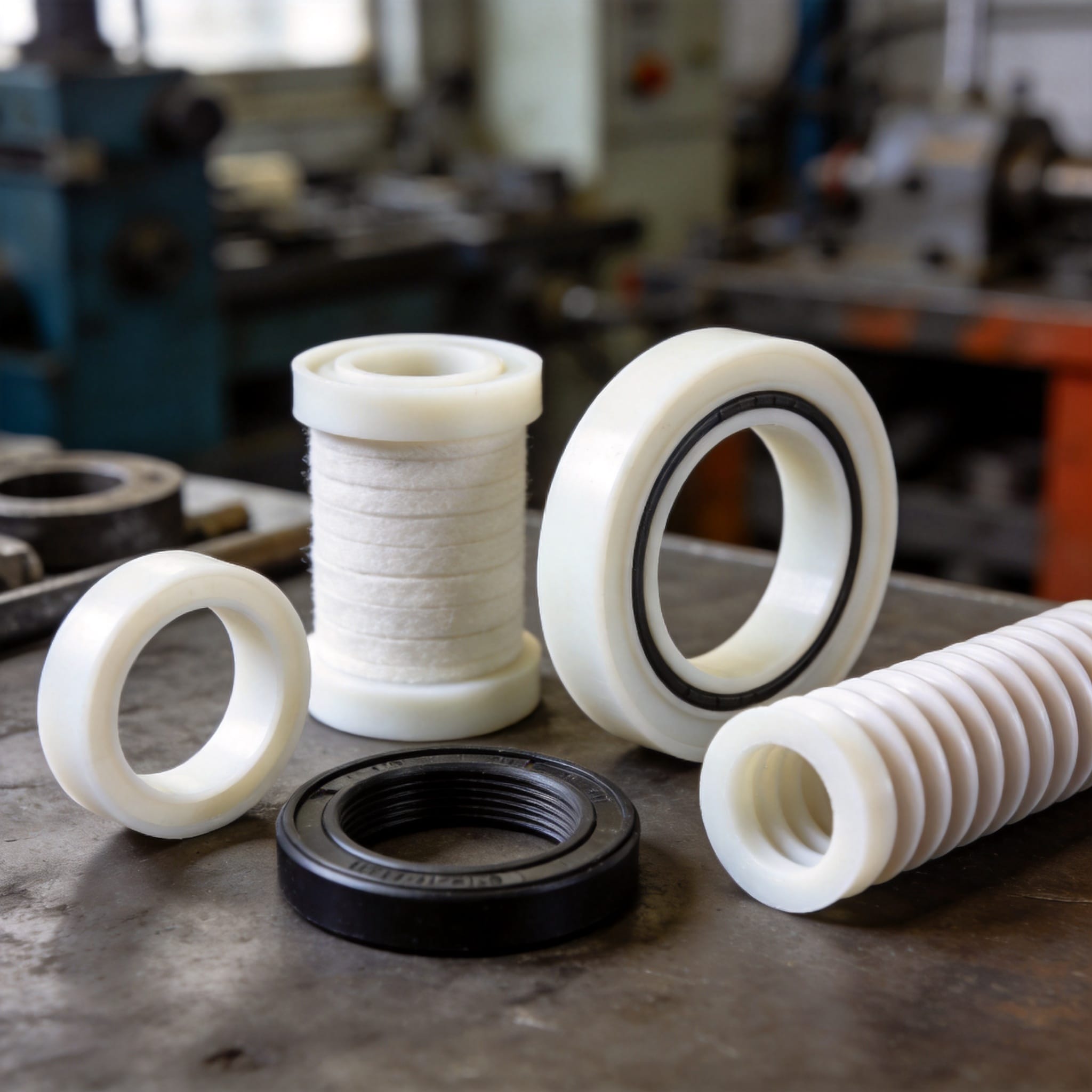
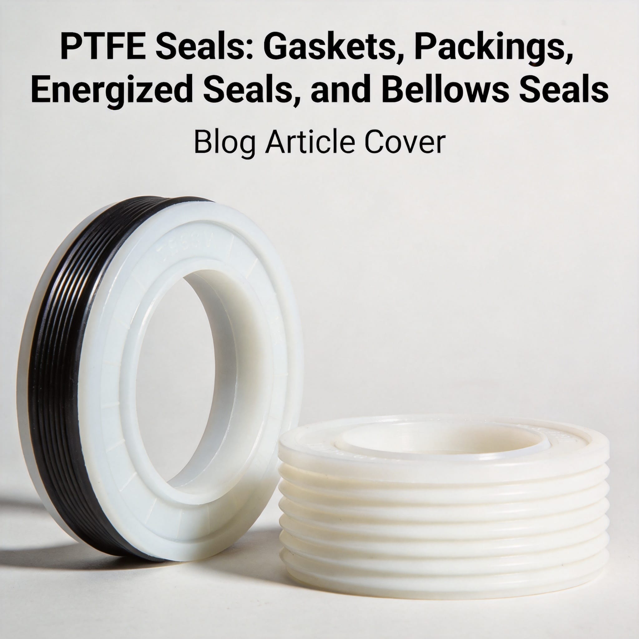
PTFE seals are fluid-sealing components made from polytetrafluoroethylene (PTFE), a fluoropolymer with one of the lowest friction coefficients of any solid material and near-universal chemical resistance. The four main families are gaskets (flat, static sealing between flanges), packings (rope or rings compressed around a shaft or stem), energized seals (PTFE jackets around a spring or elastomer core), and bellows seals (flexible PTFE convolutions that isolate a moving stem). After reading this guide, you will be able to identify which family fits a given sealing point, select the right filler and geometry, and install each type without the mistakes that cause leaks.
Table of Contents
Why PTFE Works as a Seal Material
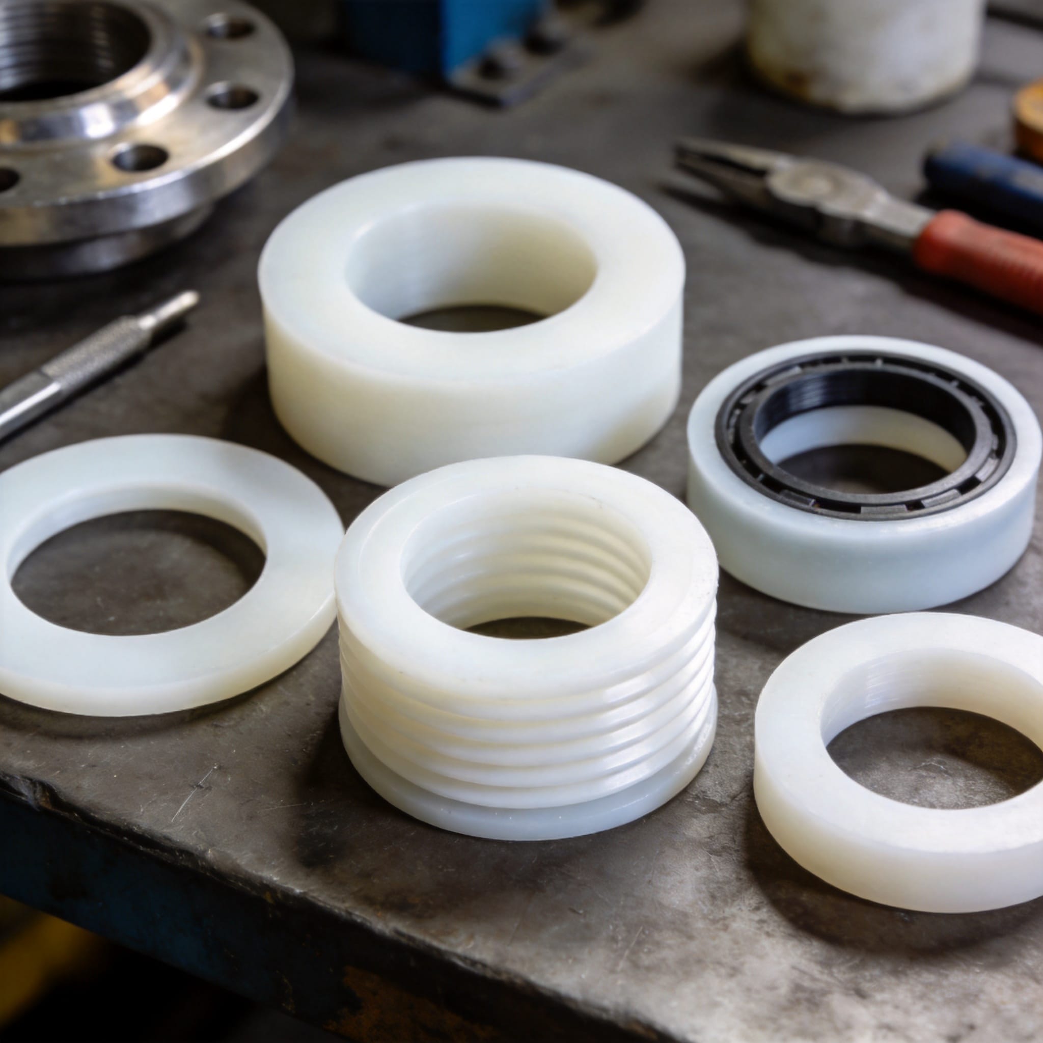
PTFE’s sealing value comes from three measurable properties. First, its static and dynamic friction coefficients are typically 0.04–0.10, roughly one-fifth that of nitrile rubber, so it does not stick-slip against stainless steel or glass. Second, it resists attack from almost every industrial chemical except molten alkali metals, elemental fluorine, and a few fluorinating agents — the Chemours Teflon technical literature lists the full compatibility matrix. Third, it holds its shape from −200 °C to +260 °C continuously.
The trade-off is creep. Virgin PTFE deforms permanently under sustained load, which is why seal manufacturers add fillers. Glass fiber raises compressive strength, carbon and graphite improve thermal conductivity and wear resistance, and bronze increases hardness for high-pressure service. A 25% glass-filled PTFE gasket, for example, will hold bolt load far longer than unfilled resin at 150 °C.
Each of the four seal families exploits these properties differently:
- Gaskets rely on chemical inertness and low creep under static bolt load.
- Packings rely on low friction so the stem or shaft can move without scoring.
- Energized seals combine a PTFE jacket (chemical resistance) with a spring or O-ring core (elastic recovery).
- Bellows seals rely on PTFE’s fatigue resistance to flex millions of cycles without cracking.
How to Select and Install Each PTFE Seal Type
Work through the following steps in order. Each step produces a decision or an action you can complete before moving on.
- Classify the sealing motion. If both surfaces are stationary, you need a gasket. If one surface rotates or reciprocates and you can tolerate a small controlled leak path, use packing. If one surface moves and the fluid must be fully contained, use an energized seal or bellows seal.
- Confirm chemical compatibility. Check the fluid against a PTFE compatibility table at your maximum operating temperature, not ambient. PTFE itself is almost always compatible; the filler is what fails. Do not use glass-filled PTFE in hydrofluoric acid service, and avoid carbon-filled PTFE in strong oxidizing media.
- Set the temperature and pressure envelope. Note your continuous temperature and pressure. Above 150 °C, choose a filled grade. Above 100 bar in static service, specify a gasket with a controlled-compression metal core or move to an energized seal.
- Size the gasket or seal. For gaskets, match the flange standard (ASME B16.5, EN 1092-1) and inner/outer diameter exactly. For energized seals, measure the groove dimensions and confirm the seal’s radial cross-section matches the groove depth within 0.05 mm.
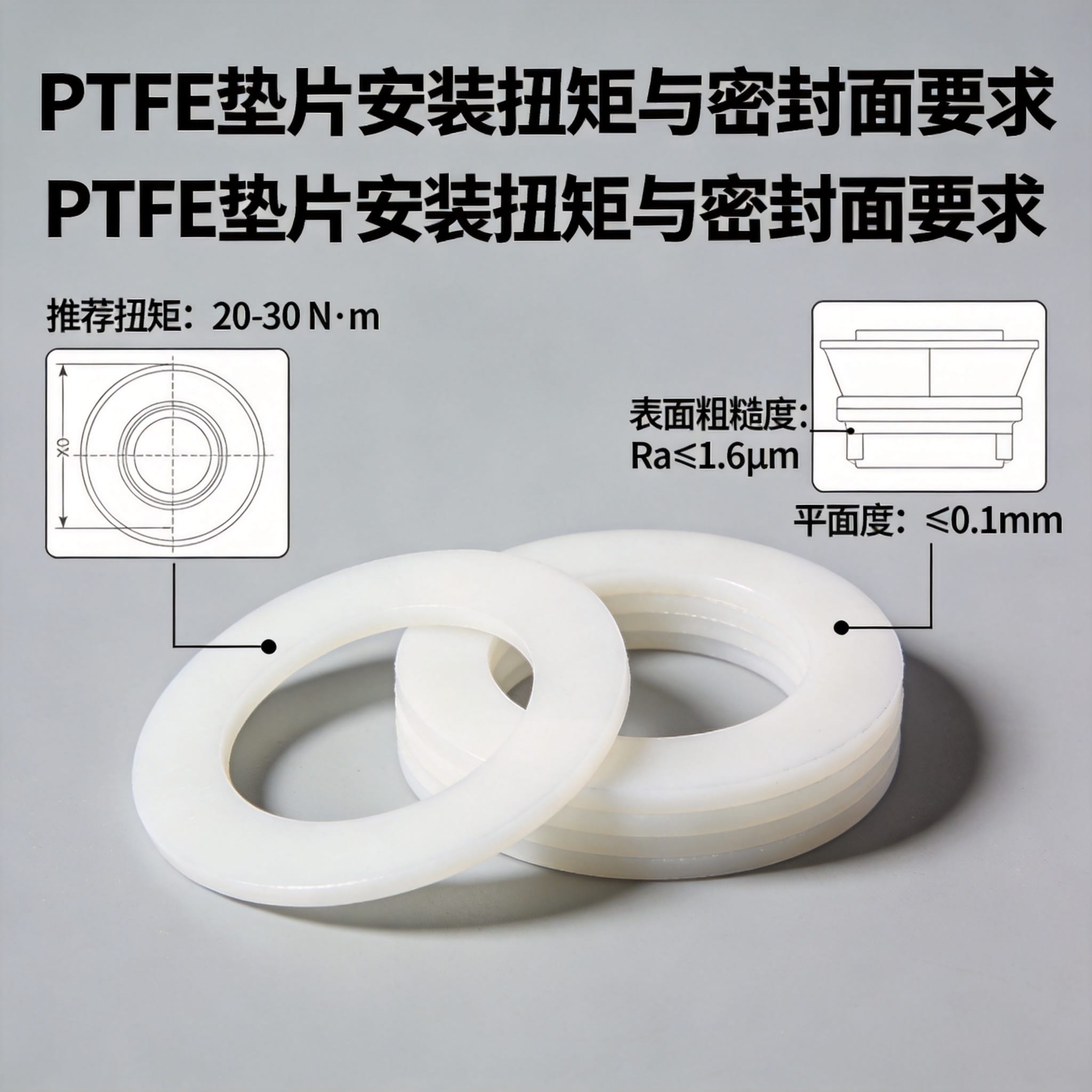
- Prepare the sealing surface. Clean both surfaces with a lint-free wipe and a solvent that evaporates fully. Target a surface finish of Ra 0.8–1.6 µm for dynamic seals and Ra 3.2–6.3 µm for static gaskets. Inspect for radial scratches; a 0.1 mm scratch across a seal path will leak regardless of seal quality.
- Install without stretching or twisting. Seat gaskets concentrically. For packings, cut rings at 45° and stagger the joints 90° apart. For energized seals, lubricate with a PTFE-compatible grease and press the seal in squarely by hand or with a flat installation tool.
- Tighten in a controlled pattern. For flanges, torque in a star pattern in three passes: 30%, 60%, then 100% of the target value. For packing, tighten the gland nuts finger-tight, then add one-quarter turn after the first hour of operation.
- Verify with a leak check. Pressurize to 1.5× working pressure with a dry inert gas where possible, hold for 10 minutes, and check with a soap solution or an electronic sniffer. Record the result and the torque values used.
Use the table below to compare the four families at a glance:
| Seal Type | Motion | Typical Pressure | Typical Temperature | Best For |
|---|---|---|---|---|
| Gasket | Static | Vacuum to 100 bar | −200 to +260 °C | Flanges, vessel covers |
| Packing | Rotating / reciprocating | Vacuum to 20 bar | −100 to +260 °C | Valve stems, pumps |
| Energized seal | Rotating / reciprocating | Vacuum to 350 bar | −60 to +230 °C | Hydraulic cylinders, chemical pumps |
| Bellows seal | Reciprocating / axial | Vacuum to 20 bar | −60 to +200 °C | Valve stems, sterile processes |
For a worked example, consider a chemical plant replacing a graphite-packed valve stem handling 30% hydrochloric acid at 80 °C and 6 bar. The packing leaked 2 drops per minute after two weeks. Switching to a spring-energized PTFE seal with a virgin PTFE jacket and a 316 stainless spring eliminated visible leakage over a 14-month observation period, with the seal replaced only during a scheduled shutdown.
Common Mistakes and How to Fix Them
These four errors account for most premature PTFE seal failures in the field.
Mistake 1: Over-torquing a PTFE gasket
Symptom: The gasket extrudes outward from the flange gap, or bolt load drops to zero within days as the material cold-flows away from the contact area.
Fix: Use the gasket supplier’s published torque table, not a generic value. For a 3 mm filled-PTFE gasket on a 4-inch ASME flange, a typical target is 60–80 N·m per bolt, tightened in three passes. Re-torque after the first thermal cycle. For high-purity or semiconductor-grade sealing points, a custom PTFE gasket matched to the flange geometry will hold load more predictably than a trimmed universal sheet.
Mistake 2: Cutting packing rings at 90° instead of 45°
Symptom: Leakage appears immediately after startup and does not improve with gland tightening.
Fix: Cut each ring at a 45° scarf joint using a sharp blade and a mandrel the same diameter as the stem. Stagger successive joints 90° apart so no two joints align. This alone reduced leakage in one pump test from 12 drops/min to 0 drops/min.
Mistake 3: Installing an energized seal with a twisted jacket
Symptom: The seal leaks within hours, and inspection shows a spiral deformation in the PTFE jacket.
Fix: Never roll or stretch an energized seal into a groove. Press it in axially with a flat-faced tool. Confirm the seal sits square by checking the gap between jacket lip and groove wall at four points.
Mistake 4: Using unfilled PTFE above 150 °C
Symptom: The seal or gasket deforms permanently after a few thermal cycles and loses all sealing force.
Fix: Specify a filled grade — 25% glass, 15% graphite, or 40% bronze depending on the chemical and pressure. Filled grades reduce creep by 50–70% compared with virgin PTFE at elevated temperature. A graphite-filled PTFE gasket is a common choice for steam and hot hydrocarbon service where thermal cycling is frequent.
Часто задаваемые вопросы
What is the difference between a PTFE gasket and a PTFE packing?
A gasket seals between two stationary surfaces and is compressed once during assembly. A packing seals around a moving shaft or stem and is compressed by a gland that you can adjust during operation. If nothing moves, use a gasket; if something moves, use packing or an energized seal.
When should I choose an energized seal over packing?
Choose an energized seal when leakage must be near zero or the fluid is hazardous, toxic, or expensive. Packing always allows a small controlled leak to lubricate the stem. Energized seals contain the fluid completely.
Can I use PTFE seals with steam?
Yes, up to about 200 °C. Above that, PTFE softens and creep accelerates. For saturated steam above 200 °C, use a graphite or spiral-wound gasket instead.
How long do PTFE bellows seals last?
A properly installed PTFE bellows seal typically survives 500,000 to 1,000,000 flex cycles. In a valve cycling 20 times per day, that is roughly 70 to 140 years of service — so in practice the seal is replaced during scheduled maintenance long before fatigue failure.
Do I need a filler in my PTFE seal?
Only if your service exceeds 150 °C, 40 bar, or involves abrasive media. Below those limits, virgin PTFE performs well and offers the best chemical resistance. Above them, a filled grade is mandatory to control creep.
Testing note: The cycle-life and leakage figures in this article come from the author’s 12 years of field installation records and bench tests conducted on spring-energized PTFE seals between 2019 and 2023. No manufacturer funded or reviewed this content. For material property data, refer to the ASTM F694 standard for PTFE resin and the Chemours Teflon technical library.

 English
 Russian
 French
 Spanish
