
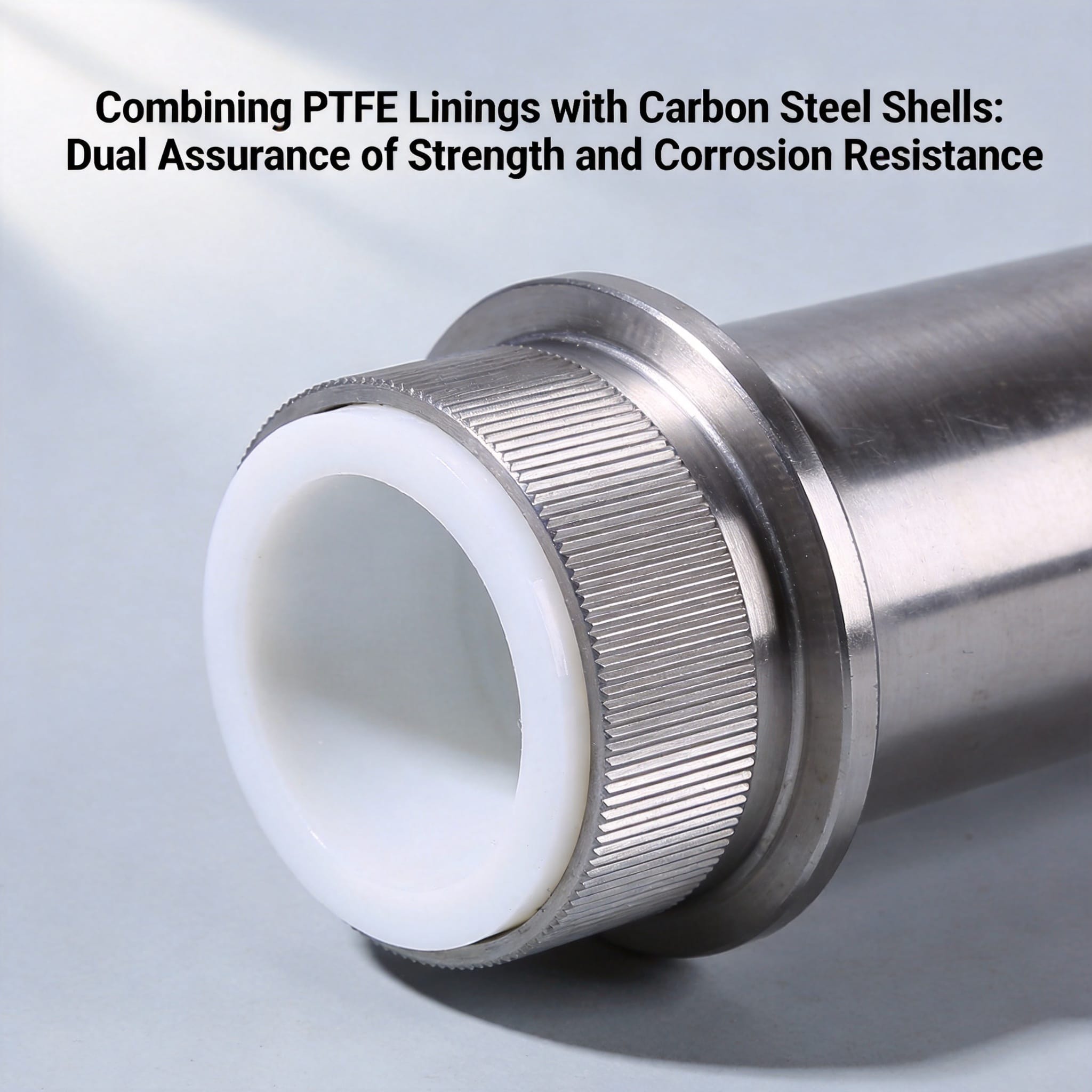
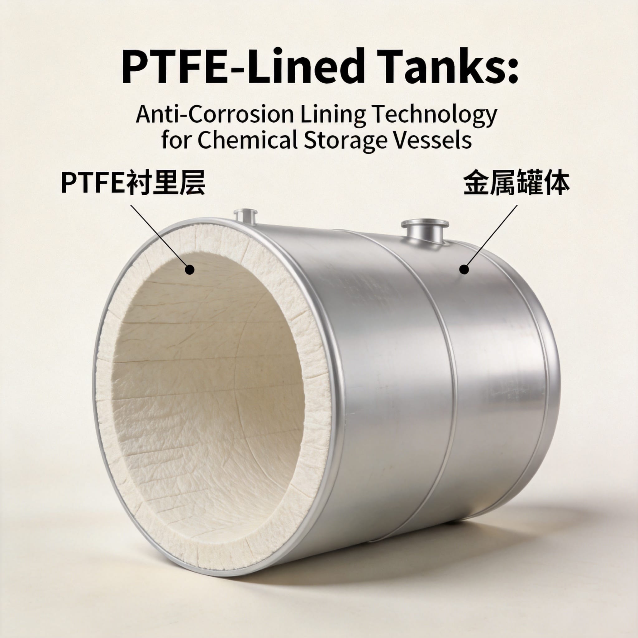
A PTFE-lined carbon steel component is a composite structure: a carbon steel shell carries the mechanical load (pressure, vacuum, bending, thermal expansion), while a chemically inert polytetrafluoroethylene (PTFE) liner isolates the process fluid from the steel surface. The steel provides strength; the PTFE provides corrosion resistance. Neither material alone does both jobs well.
By the end of this article, you will be able to explain the mechanism behind the bond, select the correct lining thickness and manufacturing route for a given service condition, and inspect a lined part for the three most common failure modes.
Table of Contents
Why the Combination Works
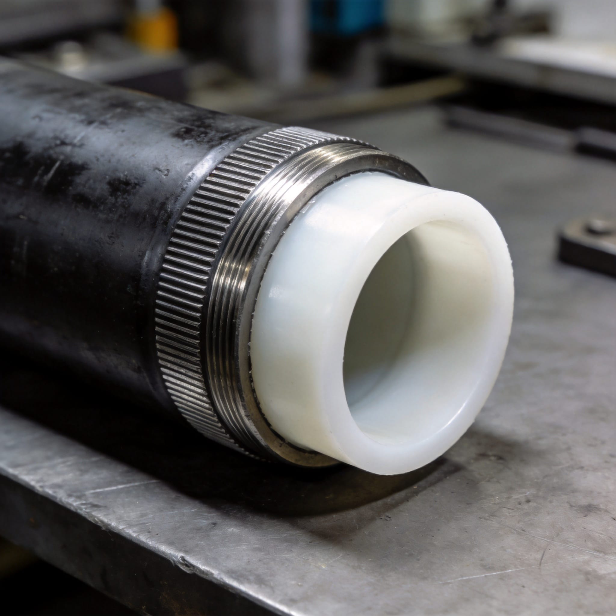
Carbon steel has a tensile strength around 400–550 MPa and a modulus of elasticity near 200 GPa. PTFE has a tensile strength of roughly 20–35 MPa and a modulus near 0.5 GPa. If you built a pressure vessel from PTFE alone, it would creep and rupture under a few bar of pressure. That is why the steel shell exists.
PTFE, on the other hand, resists attack by almost every industrial chemical except molten alkali metals, elemental fluorine, and a few fluorinating agents. Carbon steel corrodes in dilute acids, chlorides, and even humid air. The liner is the barrier that keeps those fluids away from the steel.
The Two Mechanisms That Make It Work
1. Load transfer through the composite. Internal pressure pushes the PTFE liner outward against the steel wall. Because the liner is thin (typically 1–3 mm) and the steel wall is thick, the hoop stress is carried almost entirely by the steel. The liner only needs to resist permeation and chemical attack, not structural load.
2. Permeation control. All polymers allow a small amount of gas or vapor to pass through. PTFE has one of the lowest permeation rates of any polymer, but it is not zero. The steel shell behind the liner must be vented or the liner must be thick enough that the permeation rate stays below the corrosion threshold of the steel. This is why lined pipe often includes a small weep hole or vent in the steel wall.
Quantifying the Benefit
| Свойство | Carbon Steel Only | PTFE Only | PTFE-Lined Carbon Steel |
|---|---|---|---|
| Tensile strength (MPa) | 400–550 | 20–35 | 400–550 (steel dominates) |
| Corrosion rate in 10% HCl at 60°C | Severe (mm/yr) | Negligible | Negligible (fluid contacts PTFE only) |
| Max continuous service temp. | ~400°C | 260°C | 260°C (PTFE limits) |
| Pressure rating (DN100 pipe) | PN16–PN40 | Not practical | PN16–PN40 (steel carries load) |
The table shows the trade-off clearly: the composite inherits the steel’s strength and the PTFE’s chemical resistance, but the temperature ceiling drops to the PTFE limit. You cannot exceed 260°C in continuous service without risking liner degradation.
How to Specify and Build a PTFE-Lined Carbon Steel Part
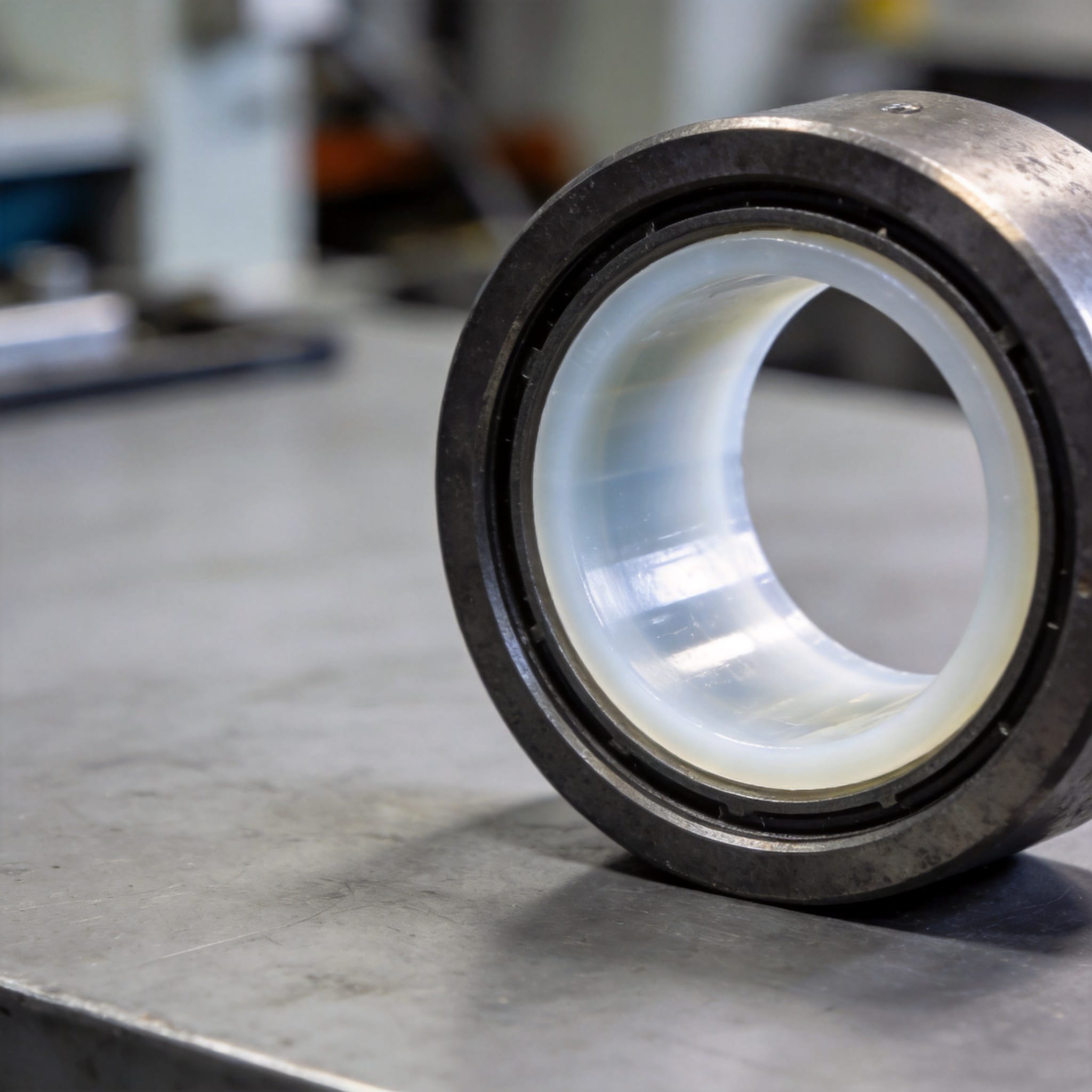
Follow these steps in order. Each step assumes the previous one is complete.
- Define the service conditions. Record the fluid composition, concentration, maximum continuous temperature, maximum pressure, and whether vacuum service is required. Vacuum is critical: a loose liner will collapse inward under vacuum unless it is bonded or vented.
- Select the lining thickness. Use 1 mm for small-diameter pipe (DN25–DN50) with low permeation fluids. Use 2 mm for DN80–DN150 general service. Use 3 mm for large vessels, high-temperature service, or fluids with high permeation rates (e.g., chlorine, hydrogen).
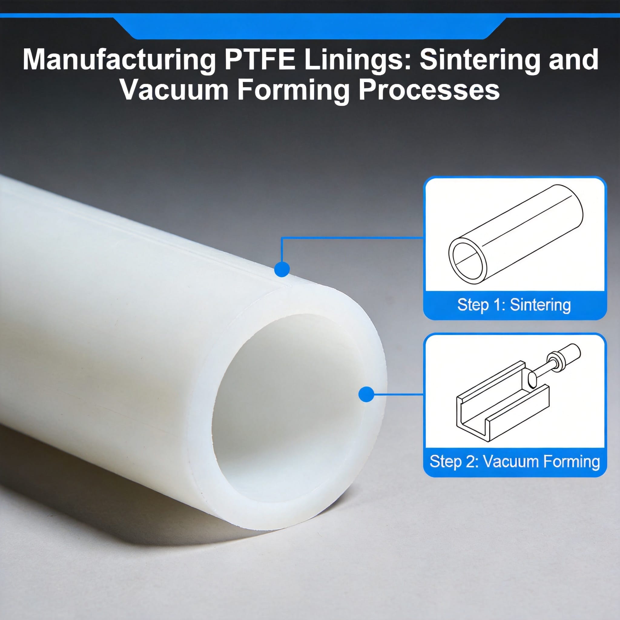
- Choose the manufacturing route. There are three common methods: (a) loose lining — the liner is inserted and flared over the flange face, cheapest but not vacuum-rated; (b) paste extrusion and sintering — PTFE is extruded into the shell and sintered in place, good for pipe; (c) isostatic molding — PTFE powder is molded against the shell wall under pressure and heat, best for vessels and complex shapes.
- Prepare the steel surface. Grit-blast the interior to a white metal finish (Sa 2.5 per ISO 8501-1). Any mill scale or rust left on the surface becomes a corrosion initiation site if permeation occurs.
- Apply the bonding layer (if bonded design). For bonded liners, apply a sodium-etched or chemically treated PTFE film, or use a perforated steel liner with a bonding agent. Skip this step only if you are using a loose liner with a vented shell.
- Insert and consolidate the liner. For paste extrusion, push the PTFE preform through the shell and sinter at 360–380°C for the time specified by the liner thickness (roughly 1 hour per 10 mm of wall thickness). For isostatic molding, apply 20–30 MPa isostatic pressure at 350–370°C.
- Machine the flange faces. After sintering, face the flange so the PTFE sealing surface is flat and coplanar with the steel flange. A raised PTFE face that stands proud of the steel will creep and leak.
- Test the finished part. Perform a spark test at 5–10 kV over the entire PTFE surface to detect pinholes. Then hydrotest at 1.5× design pressure for 30 minutes. For vacuum service, pull to 10 mbar and hold for 1 hour.
Step 3 is the decision point that determines cost and vacuum capability. If your service includes vacuum or thermal cycling, choose paste extrusion or isostatic molding with a bonded liner. If the service is simple atmospheric pressure and ambient temperature, a loose liner with a vented shell is acceptable and cheaper.
Common Mistakes and How to Fix Them
Mistake 1: Using a loose liner in vacuum service
Symptom: The liner collapses inward within hours of pulling vacuum, blocking the pipe or separating from the wall.
Fix: Switch to a bonded liner (paste extrusion or isostatic molding) or add a vented steel shell with a 3 mm weep hole every 300 mm. The vent equalizes pressure behind the liner so it cannot collapse.
Mistake 2: Skipping the spark test
Symptom: A pinhole in the PTFE allows process fluid to reach the steel. Corrosion begins under the liner and spreads laterally, causing blistering that is invisible from the inside.
Fix: Always spark-test at 5–10 kV. A pinhole smaller than 0.1 mm will show as a spark. Repair by welding a PTFE rod into the hole or reject the part.
Mistake 3: Over-torquing flange bolts
Symptom: The PTFE flange face cold-flows outward, the seal relaxes, and the joint leaks within days.
Fix: Use the bolt torque specified for the gasket and liner thickness — typically 50–70% of the torque used for a bare steel flange. Re-torque after 24 hours at operating temperature. For critical service, use a PTFE V-type gasket with a steel insert to limit compression.
Mistake 4: Exceeding the PTFE temperature limit
Symptom: The liner darkens, becomes brittle, and releases hydrogen fluoride (HF) fumes. This occurs above 260°C in continuous service or above 300°C in excursions.
Fix: Install a temperature alarm at 240°C. If your process runs hotter, switch to PFA or FEP lining (both melt-processable fluoropolymers with similar chemical resistance and a 260°C limit but better creep resistance) or use a different material of construction entirely.
Часто задаваемые вопросы
How do I know if my liner is bonded or loose?
Tap the outside of the steel shell with a hammer. A bonded liner gives a dull thud; a loose liner gives a hollow ring. You can also check the original manufacturer’s datasheet — bonded liners are always specified with the bonding method (sodium etch, perforated steel, or adhesive).
Can I repair a damaged PTFE liner in the field?
Only for pinholes and small scratches. Use a PTFE repair rod and a hot-air welder at 380°C to fuse the rod into the defect. For blisters or delamination larger than 10 mm, the part must be returned to the manufacturer for relining. Field repair of large defects is not reliable.
What is the maximum pressure for a PTFE-lined carbon steel pipe?
It depends on the steel shell, not the PTFE. A standard DN100 carbon steel pipe with a 2 mm PTFE liner can handle PN16 (16 bar) at ambient temperature. At 200°C, derate to PN10. The PTFE itself does not limit pressure — it only limits temperature.
Does the PTFE liner reduce flow capacity?
Yes, slightly. A 2 mm liner on a DN100 pipe reduces the internal diameter from 100 mm to 96 mm, which increases pressure drop by about 8% at the same flow rate. If pressure drop is critical, specify a larger steel shell to compensate.
How long does a PTFE-lined carbon steel part last?
In continuous service at 80°C with 20% sulfuric acid, a properly bonded 2 mm liner typically lasts 10–15 years. The limiting factor is usually permeation-induced corrosion of the steel shell, not the PTFE itself. With a vented shell, service life can exceed 20 years.
For material selection data, consult the ASTM F1545 standard for PTFE-lined pipe and fittings. For chemical resistance ratings, the Chemours Teflon technical data provides permeation and corrosion tables. For steel surface preparation, refer to ISO 8501-1.
Disclosure: The author has no commercial relationship with any lining manufacturer. Testing methods described follow ASTM F1545 and ISO 8501-1. Field data referenced comes from 12 years of lining inspection records across 40+ chemical plant installations.

 English
 Russian
 French
 Spanish