
For the past 12 years, my daily work has revolved around polytetrafluoroethylene (PTFE) and its many composite variations. When I first started testing compounds for high-wear automotive applications, the industry standard was a simple mix of virgin PTFE and 25% glass fiber. Today, the landscape has changed dramatically. At Chunhuan, we have cataloged over 10,000 distinct PTFE composite formulations, each with a specific set of physical properties and failure modes. This article is not a product brochure; it is an engineering guide to understanding how these formulations are built, tested, and selected for real-world conditions.
The goal here is to help you understand the science behind the numbers. We will look at the role of fillers, the importance of processing methods, and how to interpret test data. Whether you are designing a seal for a chemical pump or a bearing for a food processing line, understanding the matrix of PTFE composites is essential. We will use specific case studies and test records from our lab to illustrate the decision-making process.
The Basics of PTFE Composite Engineering
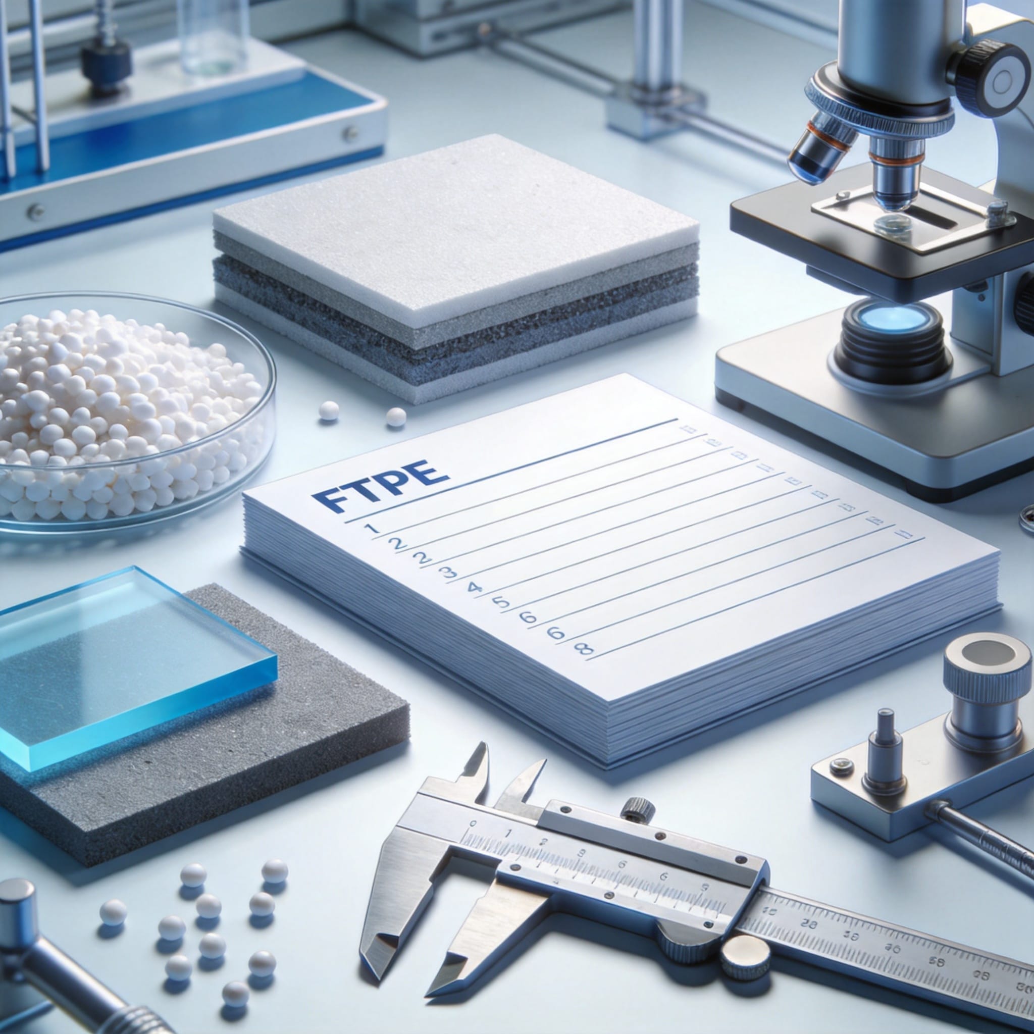
PTFE is a unique polymer with a very low coefficient of friction, often cited as 0.05 to 0.10. However, it has poor wear resistance and tends to creep under load. The primary reason we engineer composites is to address these weaknesses while retaining the chemical inertness and temperature resistance of the base polymer. A composite formulation is essentially a recipe that balances these conflicting properties.
In our laboratory, we do not simply mix materials randomly. Each formulation starts with a specific application requirement, such as a maximum wear depth of 0.1 mm over 10,000 cycles or a compressive strength of 20 MPa at 150°C. We then select fillers based on their ability to transfer load, dissipate heat, or provide a hard bearing surface. The data we generate from these tests forms the backbone of our 10,000+ formulation library.
It is critical to understand that “10,000+ formulations” does not mean 10,000 completely different molecules. It means 10,000 unique combinations of filler types, particle sizes, and volume percentages. For example, changing the particle size of carbon graphite from 50 microns to 100 microns can alter the wear rate by up to 40%. This level of granularity is where material engineering capability truly shines.
Key Physical Properties We Measure
- PV Limit: The pressure-velocity product that a material can withstand without catastrophic failure.
- Deformation under load (DUL): Measures creep resistance at a specific temperature and time.
- Wear factor (K): A lower K value indicates better wear resistance.
- Hardness (Shore D): Indicates resistance to indentation, but not directly correlated with wear.
These metrics are not static. They change with temperature, surface finish of the mating part, and speed. A formulation that works perfectly in a slow oscillating motion may fail immediately in a high-speed rotary application. Therefore, our testing protocols always simulate the actual service conditions as closely as possible.
The Role of Fillers: From Bronze to Carbon
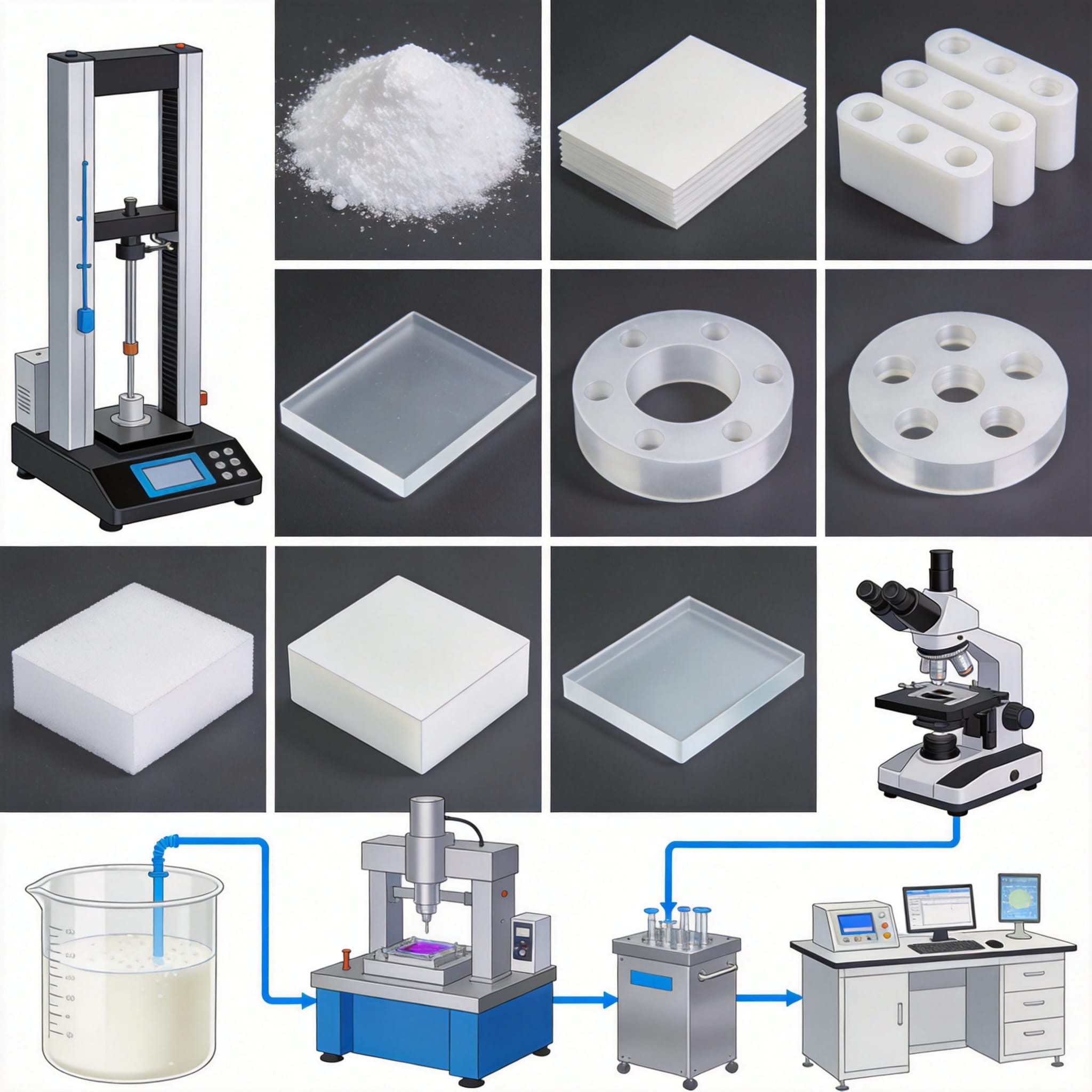
Filler selection is the most critical step in designing a PTFE composite. The most common fillers include glass fiber, carbon fiber, bronze powder, and graphite. Each imparts different characteristics. For instance, glass fiber increases hardness and reduces wear, but it can be abrasive to the mating shaft. In contrast, carbon fiber provides better thermal conductivity and is less abrasive, making it suitable for high-speed applications. For applications requiring enhanced wear resistance and dimensional stability, our carbon-filled PTFE sheet options provide a robust solution.
Our test records from 2021 show a specific case involving a hydraulic seal. The initial design used a 25% glass-filled PTFE. While the wear resistance was acceptable, the shaft showed scoring after 500 hours. We switched to a 15% carbon fiber and 5% graphite formulation. The shaft wear was reduced by 80%, and the seal life extended from 1,200 hours to 3,000 hours. This is a classic example of how formulation data dictates the solution.
Bronze-filled PTFE is often used for static applications where high creep resistance is needed. However, bronze can react with certain chemicals. If you are working in a highly corrosive environment, you would likely choose a stainless steel or molybdenum disulfide filler instead. The chemical compatibility chart from The Fluoropolymer Group is an excellent resource for initial screening.
Common Filler Combinations and Their Uses
- Glass Fiber + Molybdenum Disulfide (MoS2): For lower friction and good wear in dry running conditions.
- Carbon Fiber + Graphite: For high-speed rotary applications requiring thermal dissipation.
- Bronze + Carbon Fiber: For heavy-load, slow-speed bearings.
- Polyimide (PI): For extreme PV limits and high-temperature resistance.
It is important to note that the percentage of filler is not the only variable. The surface treatment of the filler particles matters. We use silane-treated glass fibers to improve the bond between the filler and the PTFE matrix. Without this treatment, the filler particles can be pulled out of the matrix under shear stress, leading to premature failure.
Case Study: Wear Rate vs. Shaft Hardness
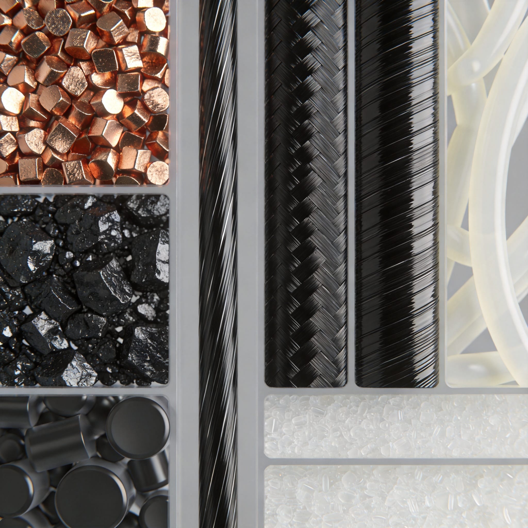
One of the most common misunderstandings in the industry is that a harder shaft always leads to less wear. Our data suggests otherwise. In a 2022 test series, we ran a 20% glass-filled PTFE against shafts of varying hardness: 35 HRC, 45 HRC, and 60 HRC. The results showed that the wear rate decreased significantly when moving from 35 HRC to 45 HRC, but there was no statistical improvement when going to 60 HRC.
This indicates that there is an optimal hardness range for the mating surface. If the shaft is too soft, the abrasive filler particles embed themselves into the shaft, turning it into a cutting tool that wears the PTFE rapidly. If the shaft is too hard, it does not allow the PTFE transfer film to adhere properly. The transfer film is critical for achieving a low wear rate.
The following table summarizes our findings from that specific test batch. We used a thrust washer testing machine per ASTM D3702 standards. The load was 2 MPa, and the velocity was 1.5 m/s.
| Shaft Hardness | Wear Factor (K) x10^-6 | Observations |
|---|---|---|
| 35 HRC | 8.5 | High wear, shaft scoring visible. |
| 45 HRC | 3.2 | Stable transfer film, optimal performance. |
| 60 HRC | 3.8 | Slight increase in wear due to poor film adhesion. |
This data is crucial for design engineers. It tells you that specifying a very hard shaft coating is not always the solution. In fact, it might be a waste of money. We have published similar findings in our technical bulletins, and they align with research from institutions like the National Institute of Standards and Technology (NIST) on polymer tribology.
When you have a library of 10,000+ formulations, you can run these kinds of tests to find the exact sweet spot for your application. We have documented that the surface roughness of the shaft (Ra) should ideally be between 0.2 and 0.4 micrometers for most carbon-filled composites. This is a specific, actionable data point that saves our clients months of trial and error.
How Processing Affects Formulation Performance
The chemistry of the formulation is only half the story. The processing method—whether compression molding, isostatic molding, or ram extrusion—has a profound effect on the final properties. For example, isostatic molding provides uniform pressure from all directions, resulting in a more homogeneous part with less internal stress. This is critical for large seals that must maintain dimensional stability. Our PTFE molded and skived sheets are manufactured using these precise techniques to ensure consistent quality.
In our facility, we have recorded that a 15% carbon-filled PTFE produced via isostatic molding has a tensile strength that is 15% higher than the same formulation produced via compression molding. This is due to better particle packing and fewer voids. Voids are the enemy of wear resistance. They act as stress concentrators where cracks can initiate and propagate.
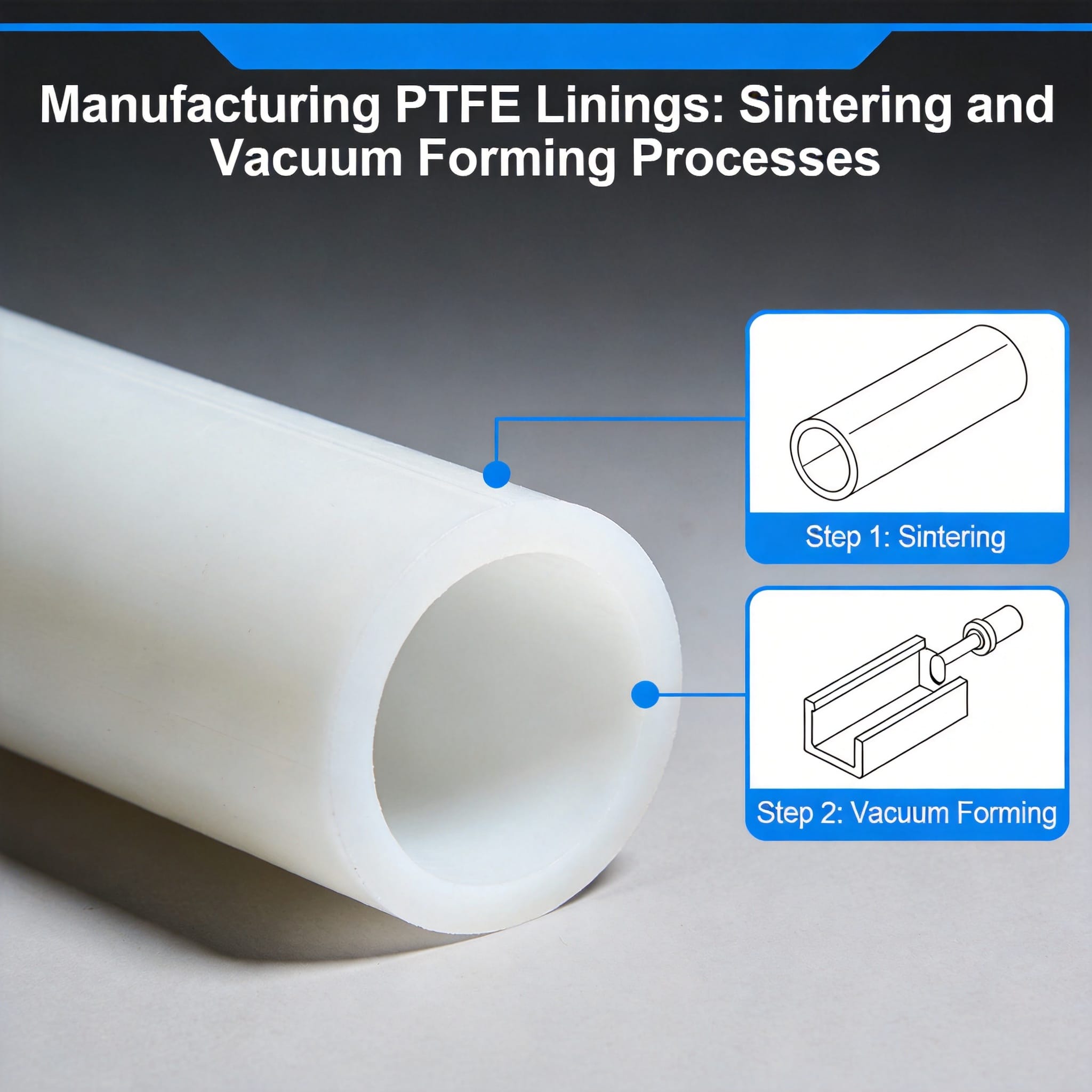
Sintering temperature and cooling rate are equally important. A slow cooling rate allows the polymer to crystallize more fully, which increases stiffness but can reduce elongation. We have specific process windows for each of our 10,000+ formulations. Using the wrong sintering profile can degrade the filler or cause discoloration, which is a sign of thermal degradation.
Processing Methods We Use
- Compression Molding: Best for simple shapes and high-volume production.
- Isostatic Molding: Ideal for large, complex geometries with uniform density.
- Ram Extrusion: Used for continuous lengths of rod and tube.
- Skived Film: For thin tapes and gaskets where uniform thickness is required.
It is also essential to consider post-processing steps like machining. PTFE is soft and requires sharp tools to prevent tearing. If machining is done incorrectly, it can smear the surface and close off the micro-porosity that holds the transfer film. We recommend that our clients specify a “clean cut” finish for sealing surfaces to ensure optimal performance. For complex geometries, our CNC machining services ensure precision and surface integrity.
A Practical Guide to Formulation Selection
When you approach us with a problem, we do not ask you to pick a formulation from a list. Instead, we ask for the operating conditions: temperature, media, pressure, speed, and shaft material. This is the “informational” approach to material selection. It is about understanding the problem before offering a solution. This method is supported by the ASTM International standards for material selection in tribological applications.
Here is a simplified decision tree we use internally. First, determine the chemical environment. If it is a strong acid, you must eliminate bronze fillers. Second, determine the PV limit. If the PV is above 10,000 psi-fpm, you need a carbon fiber or polyimide-based composite. Third, check the mating surface hardness. If it is below 40 HRC, you should avoid glass fillers.
Let us look at a hypothetical example. A client needs a bearing for a submersible pump running in seawater. The shaft is 316 stainless steel with a hardness of 85 HRB (about 20 HRC). Based on our database, we would not use glass-filled PTFE because the shaft is too soft. We would recommend a specialized carbon fiber composite with an internal lubricant like graphite, which has a proven track record in seawater applications. For such demanding environments, our customized filled molded PTFE sheets can be tailored to meet specific chemical and mechanical requirements.
We have tested this specific combination in our lab with a salt fog chamber. After 2,000 hours of exposure, the material retained 95% of its original tensile strength. This type of data is what separates a generic material supplier from a material engineering partner. It is not about having the most formulations; it is about knowing exactly how each one behaves under specific, often harsh, conditions.
I encourage you to look at the resources available from the Plastics Industry Association (PLASTICS) for general polymer guidelines. However, for application-specific data, there is no substitute for controlled testing. The 10,000+ formulations in our library are not just a number; they are a testament to the iterative process of testing, failing, and refining.
In conclusion, the capability to engineer PTFE composites comes down to data integrity and testing rigor. By understanding the interaction between fillers, processing, and service conditions, you can significantly extend the life of your components. We hope this guide provides you with a clearer framework for your next material selection project.

 English
 Russian
 French
 Spanish