
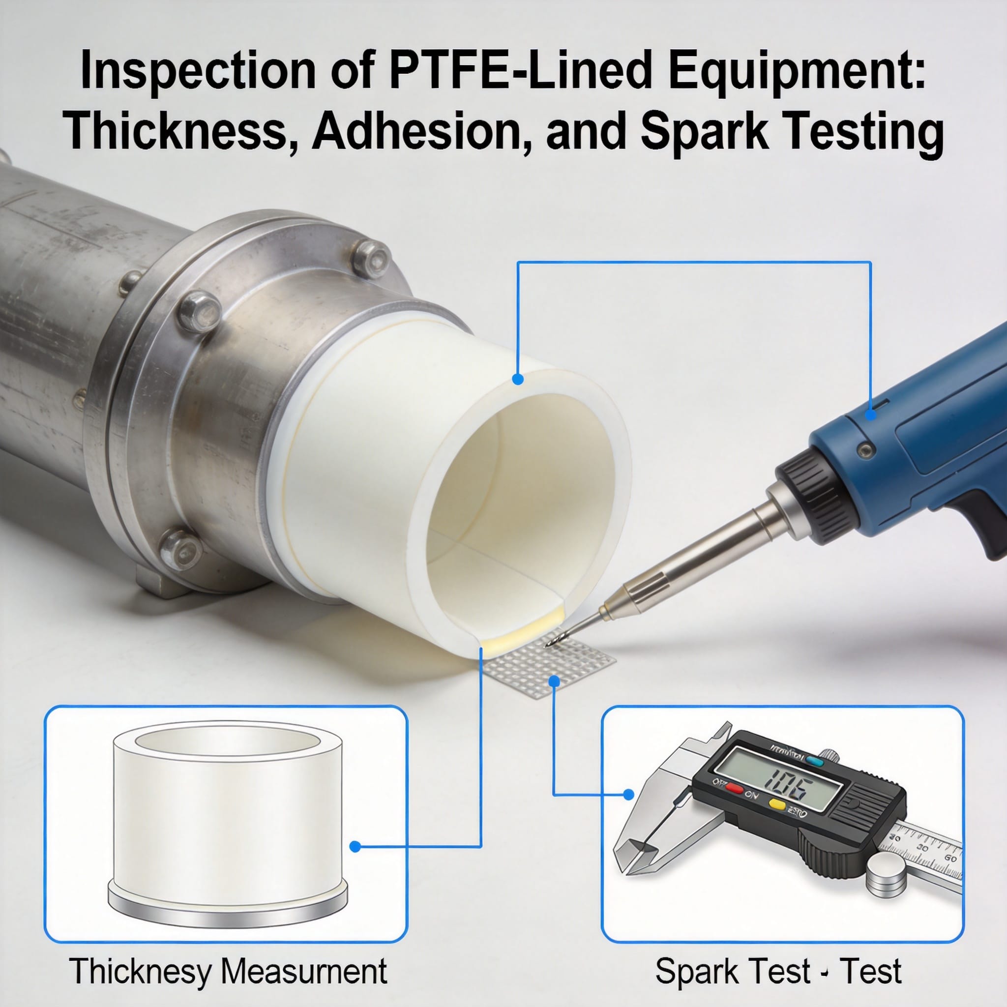
PTFE-lined equipment inspection uses three core tests: thickness measurement with an ultrasonic gauge to verify lining wall thickness, adhesion testing to confirm the liner is bonded to the substrate, and spark testing (high-voltage holiday detection) to find pinholes and discontinuities in the lining. Pass criteria are typically: thickness within drawing tolerance, no disbonded areas, and zero sparks at the specified test voltage.
After reading this guide, you will be able to set up and run all three tests on a lined vessel, pipe, or column, interpret the readings against acceptance criteria, and document the results in a format an inspector or client will accept.
Table of Contents
Why These Three Tests Work
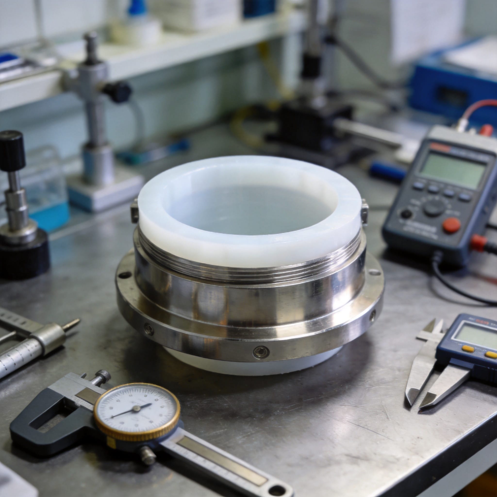
Each test targets a different failure mode, which is why you need all three instead of just one. Thickness gauging catches material loss, thin spots, and manufacturing defects in the liner itself. Adhesion testing catches areas where the liner has separated from the steel but still looks intact from the surface. Spark testing catches pinholes, cracks, and porosity that are invisible to the eye but will let corrosive media reach the substrate.
Thickness measurement works because PTFE has a known, stable speed of sound (roughly 1,350–1,400 m/s depending on grade and temperature). An ultrasonic transducer sends a pulse through the liner; the echo from the liner-to-steel interface returns a time-of-flight that the gauge converts into a thickness reading. You do not need to access the back side of the lining.
Adhesion testing works on a different principle. A bonded liner transmits a light impact as a sharp, high-frequency response; a disbonded liner transmits a dull, low-frequency “dead” response. This is the basis of both tap testing and ultrasonic bond testing. Spark testing works by applying a high voltage across a conductive brush or probe that moves over the lining surface. If the lining is continuous and non-conductive, no current flows. If there is a pinhole, the voltage arcs through to the conductive substrate and triggers an audible and visual alarm.
Industry guidance for these methods is published by ASTM International and the Association for Materials Protection and Performance (AMPP, formerly NACE). ASTM D7091 covers dry film thickness measurement of non-conductive coatings on metal, and NACE SP0188 / AMPP guidance covers holiday detection of pipeline coatings. PTFE lining inspection is typically written into project specifications based on these standards.
How to Perform the Inspection (Step by Step)
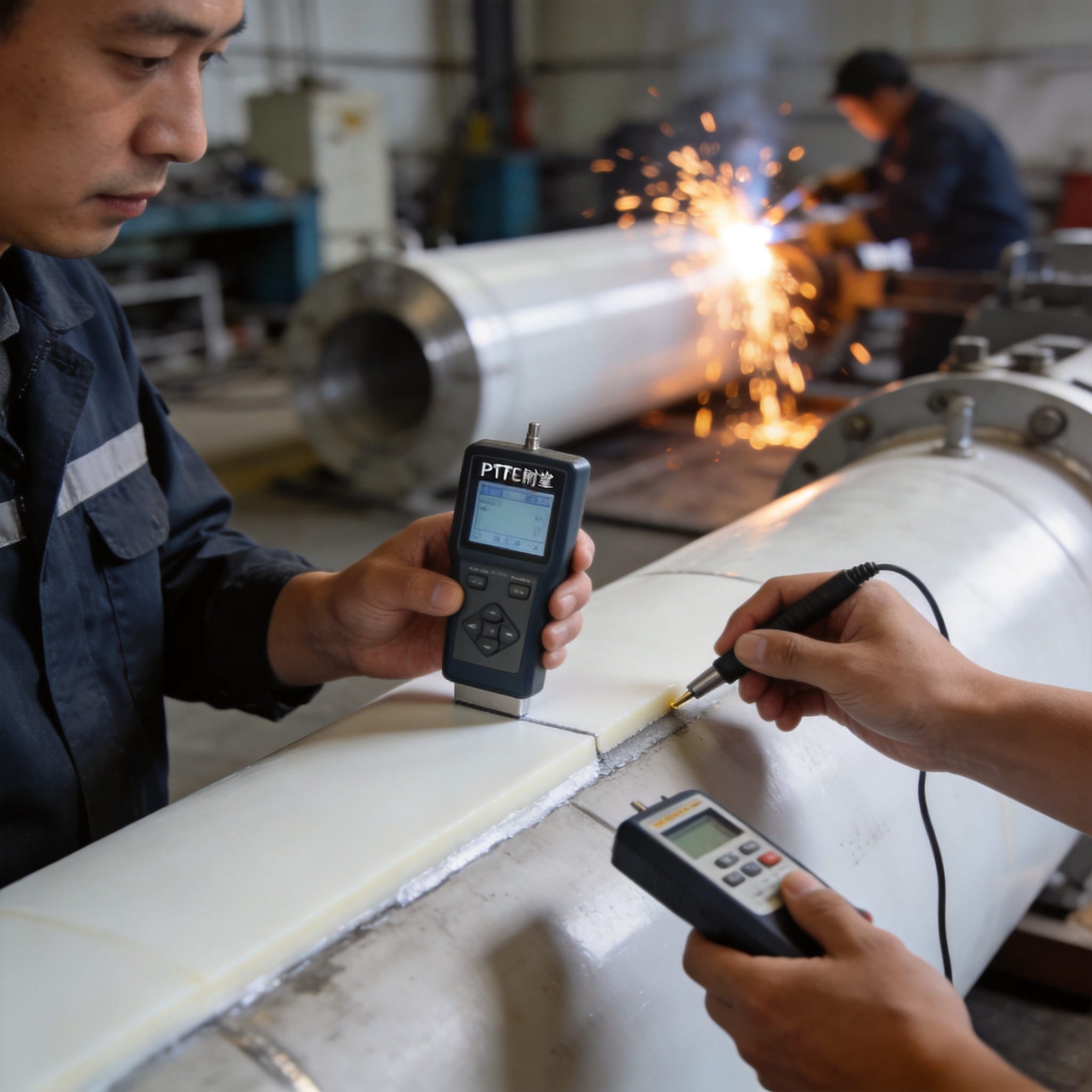
Do the tests in this order: visual first, then thickness, then adhesion, then spark. Spark testing last is deliberate — the high voltage can disturb a weak bond, so you want your adhesion baseline recorded before you run it.
Step 1: Prepare the surface and record conditions
Wipe the lining with a clean, lint-free cloth and a solvent that does not attack PTFE (isopropyl alcohol or acetone). Record ambient temperature and relative humidity. Thickness readings drift with temperature, and spark test voltage must be adjusted for humidity per the manufacturer’s chart. Note the liner grade and nominal thickness from the equipment drawing.
Step 2: Perform a visual inspection and map the surface
Divide the lined surface into a grid — for a 2 m diameter vessel, a 200 mm × 200 mm grid is a practical standard. Mark each cell with a number. Note any blisters, discoloration, scratches, or embedded foreign material. Photograph anything suspicious before you touch it with a probe.
Step 3: Calibrate the ultrasonic thickness gauge
Use a reference block of the same PTFE grade and known thickness. Set the sound velocity to match the grade. Take five readings on the block; if any deviates more than ±0.05 mm from the known value, recalibrate or replace the transducer. Record the calibration values on your inspection form.
Step 4: Measure thickness at each grid point
Press the transducer perpendicular to the surface with light, consistent pressure. Take three readings per grid point and record the lowest. Typical acceptance criteria for new PTFE lining is ±10% of nominal thickness, with no single reading below the minimum specified on the drawing. For a 3.0 mm nominal liner, that means a range of 2.7–3.3 mm and no reading below 2.7 mm. For reference on how nominal thickness is specified on PTFE plastic molded/skived sheet thick plate, check the manufacturer’s datasheet.
Step 5: Perform tap testing for adhesion
Use a small brass or plastic hammer, or a coin, and tap lightly at each grid intersection. A bonded area gives a sharp “tick”; a disbonded area gives a dull “thud.” Mark every dull response. For critical service, follow up with an ultrasonic bond tester or a pull-off adhesion test per ASTM D4541 on a test coupon.
Step 6: Set up the spark tester
Select the test voltage from the specification. A common rule for PTFE linings is 5 kV per millimeter of lining thickness, but always follow the project spec. For a 3 mm liner, that is roughly 15 kV. Connect the ground lead to a bare metal point on the substrate. Confirm the tester alarms on a known pinhole in a reference panel before you start.
Step 7: Sweep the surface with the spark probe
Move the probe at a steady 100–150 mm per second, overlapping each pass by about 25 mm. Keep the probe in contact with the surface. Any spark, audible alarm, or visible arc marks a defect. Circle the defect with a marker and continue the sweep. Do not stop on the defect — finish the pass, then come back.
Step 8: Document and disposition
Record every defect’s grid location, the test voltage, and the reading. Defects are dispositioned as repair, re-test, or reject per the project spec. A repair is typically a PTFE patch or weld rod applied by a qualified welder, followed by re-testing the repaired area with the same voltage.
Common Mistakes and How to Fix Them
Mistake 1: Using the wrong sound velocity. Symptom: thickness readings are consistently 15–25% off from the drawing. Fix: verify the sound velocity against a reference block of the same PTFE grade before every inspection. Do not trust the gauge’s default value.
Mistake 2: Spark testing with a voltage that is too high or too low. Symptom: either you get false alarms on good lining (too high) or you miss real pinholes (too low). Fix: calculate voltage from lining thickness using the project spec, and verify with a reference panel containing a known pinhole. Re-verify after any humidity change greater than 10%.
Mistake 3: Tap testing with a heavy hammer. Symptom: you create dents or cracks in the PTFE that were not there before. Fix: use a light brass or plastic hammer, or a coin, and tap with the wrist, not the arm. If you can hear the tap from 3 meters away, you are hitting too hard.
Mistake 4: Skipping the grid map. Symptom: you find a defect but cannot tell the welder where it is, and you cannot prove you inspected the whole surface. Fix: mark the grid with a paint pen or tape before you start. Every reading and every defect gets a grid coordinate.
Mistake 5: Spark testing before adhesion testing. Symptom: a weak bond fails during spark testing, and you cannot tell whether it was already weak or whether the spark test caused it. Fix: always run adhesion testing first, record the baseline, then spark test.
Preguntas frecuentes
What voltage should I use for spark testing PTFE lining?
Follow the project specification first. If none is given, a common starting point is 5 kV per millimeter of lining thickness, so a 3 mm liner is tested at about 15 kV. Always verify with a reference panel that has a known pinhole before testing production equipment.
Can I use a magnetic thickness gauge on PTFE-lined steel?
No. Magnetic gauges only work on non-conductive coatings over ferrous substrates and are not reliable on thick PTFE linings. Use an ultrasonic gauge with the correct sound velocity for the PTFE grade.
How do I know if a dull tap sound means a disbond?
Compare the suspect area to a known bonded area on the same equipment. A disbond gives a distinctly duller, lower-pitched response. If you are unsure, confirm with an ultrasonic bond tester or a pull-off test per ASTM D4541.
How often should PTFE-lined equipment be inspected?
New equipment is inspected before commissioning. In service, most operators inspect annually for mild service and every 6 months for aggressive chemical service. After any process upset, over-temperature event, or visible damage, inspect immediately regardless of schedule.
What is the acceptance criterion for thickness?
Typical new-lining acceptance is ±10% of nominal thickness with no reading below the drawing minimum. For a 3.0 mm nominal liner, that is 2.7–3.3 mm. In-service criteria are usually set by the owner based on corrosion allowance and remaining life. For liners cut from high-temp PTFE skived sheet for mechanical seals, confirm the thickness tolerance with the sheet supplier before setting acceptance limits.
With these three tests and the order above, you can inspect a lined vessel, pipe, or column and produce a defensible record. The key is calibration before measurement, adhesion before spark, and a grid map that ties every reading to a physical location. When sourcing replacement liners or patch material, specify 100% virgin PTFE skiving sheet to keep thickness and dielectric performance consistent with the original lining.


 English
 Russian
 French
 Spanish