
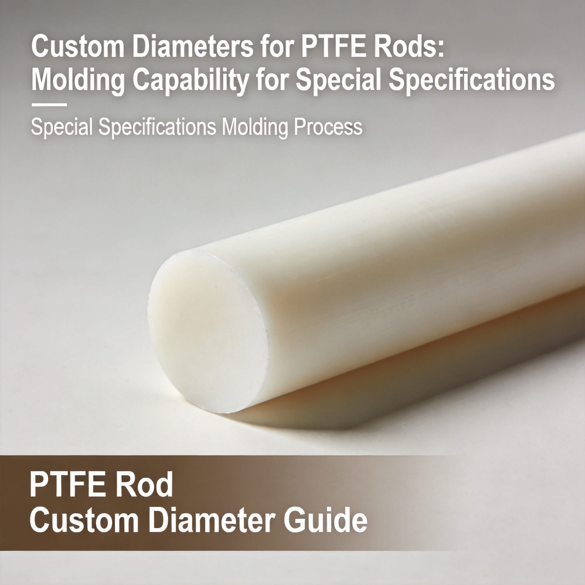
Custom diameters for PTFE rods are produced by compression molding: virgin PTFE resin is cold-pressed in a cylindrical mold sized to your target diameter, then free-sintered above 327 °C (621 °F), where the part densifies by roughly 25–30% in volume. Because PTFE cannot be melt-processed like nylon or POM, the mold cavity — not an extruder die — defines the final diameter. Practically, any diameter from about 5 mm to 500 mm is moldable, with the useful ceiling set by press tonnage and sintering oven height rather than by the polymer itself.
By the end of this guide you will be able to specify a custom PTFE rod diameter correctly, calculate the mold and preform dimensions you need, follow a complete molding sequence, and recognize the four defects that most often ruin a special-specification run.
Table of Contents
- Why Compression Molding Sets the Diameter
- How to Mold a Custom-Diameter PTFE Rod: 8 Steps
- Common Mistakes and How to Fix Them
- Diameter, Tolerance, and Capability Reference
- FAQ: Custom PTFE Rod Diameters
Why Compression Molding Sets the Diameter

PTFE has a melt viscosity around 1010 Pa·s at 380 °C — roughly a billion times thicker than molten polyethylene. It does not flow. This single property is why the entire custom-diameter industry is built on compression molding and ram extrusion rather than injection molding.
The mechanism has three stages. First, cold pressing compacts resin particles at 20–35 MPa, creating a “preform” with about 75–80% of theoretical density (2.16–2.20 g/cm³). Second, free sintering at 360–380 °C for a time proportional to the square of the wall thickness lets particle boundaries diffuse and coalesce. Third, controlled cooling at 20–40 °C/h prevents internal stress that would otherwise cause ovality or cracking.
The critical consequence for custom diameters: the mold cavity diameter is not the finished diameter. You must oversize the cavity to compensate for both shrinkage and the machining allowance you intend to remove. ASTM D4894, the standard specification for PTFE molding and extrusion materials, defines the resin grades and the test methods used to verify the result, and it is the document most molders work against.
Ram extrusion is the alternative for long, continuous lengths in a fixed diameter, but it cannot produce the one-off, unusual sizes that define “special specifications.” For a 137 mm rod in a 500 mm length, molding wins on both cost and lead time — much like the made-to-order approach behind custom 100% virgin PTFE rod products.
How to Mold a Custom-Diameter PTFE Rod: 8 Steps

Follow these steps in order. Each one is independently checkable, so you can stop and verify before committing material.
Step 1 — Fix the finished diameter and tolerance first
Write down the nominal diameter and the tolerance class before anything else. A typical as-molded tolerance is ±0.5% of diameter, or ±0.13 mm, whichever is greater. If your print calls for ±0.05 mm on a 100 mm rod, as-molded will not hold it — you must plan to machine. Decide this now; it changes every downstream number.
Step 2 — Calculate the mold cavity diameter
Use this formula:
Mold cavity diameter = (Finished diameter + machining allowance) ÷ (1 − S)
Where S is the linear shrinkage factor. For free-sintered virgin PTFE, S typically falls between 0.025 and 0.040 (2.5–4.0%). Worked example: a 100.00 mm finished rod, 1.5 mm machining allowance per side (3.0 mm total), S = 0.030.
- Target pre-sinter diameter: 100.00 + 3.00 = 103.00 mm
- Mold cavity: 103.00 ÷ (1 − 0.030) = 106.19 mm
Round the cavity to 106.2 mm. If you skip the shrinkage correction and cut a 103 mm mold, you will finish at roughly 99.9 mm and scrap the run.
Step 3 — Calculate the fill weight
Weight = π × (cavity radius)² × fill height × target green density. For a 106.2 mm cavity (radius 53.1 mm) filled to 200 mm at a green density of 1.75 g/cm³:
- Volume = 3.1416 × 53.1² × 200 = 1,771,000 mm³ = 1771 cm³
- Weight = 1771 × 1.75 = 3099 g ≈ 3.10 kg
Weigh the resin to ±0.5% of this figure. Overfilling causes delamination; underfilling causes porosity and short rods.
Step 4 — Select the resin grade
Use granular (suspension-polymerized) resin for rods above 50 mm — it flows better during pressing and gives more uniform density. Use fine-cut (emulsion) resin only for thin rods and small diameters. Match the grade to ASTM D4894 Type I, II, or III depending on your required tensile strength and elongation.
Step 5 — Press the preform
Fill the mold in 2–3 increments and tamp between each. Apply pressure at 20–35 MPa using a rate of 5–10 mm/min. Hold at full pressure for 60–120 seconds, then release slowly over at least 30 seconds. Fast decompression traps air and produces the classic “elephant skin” surface cracks.
Step 6 — Sinter with a thickness-based cycle
Heat from room temperature to 365–380 °C at 40–60 °C/h. Hold time follows the rule of thumb 1 hour per 6 mm of radius. For a 106 mm preform (53 mm radius), that is about 9 hours at peak. Then cool at 20–40 °C/h back to 200 °C before opening the oven. Total cycle for this rod: roughly 30–36 hours.
Step 7 — Measure and map the diameter
After the rod reaches room temperature, measure at six points: three heights (top, middle, bottom) and two axes 90° apart at each height. Record all twelve readings. This gives you both the mean diameter and the ovality, which is the difference between the largest and smallest reading.
Step 8 — Machine to final specification
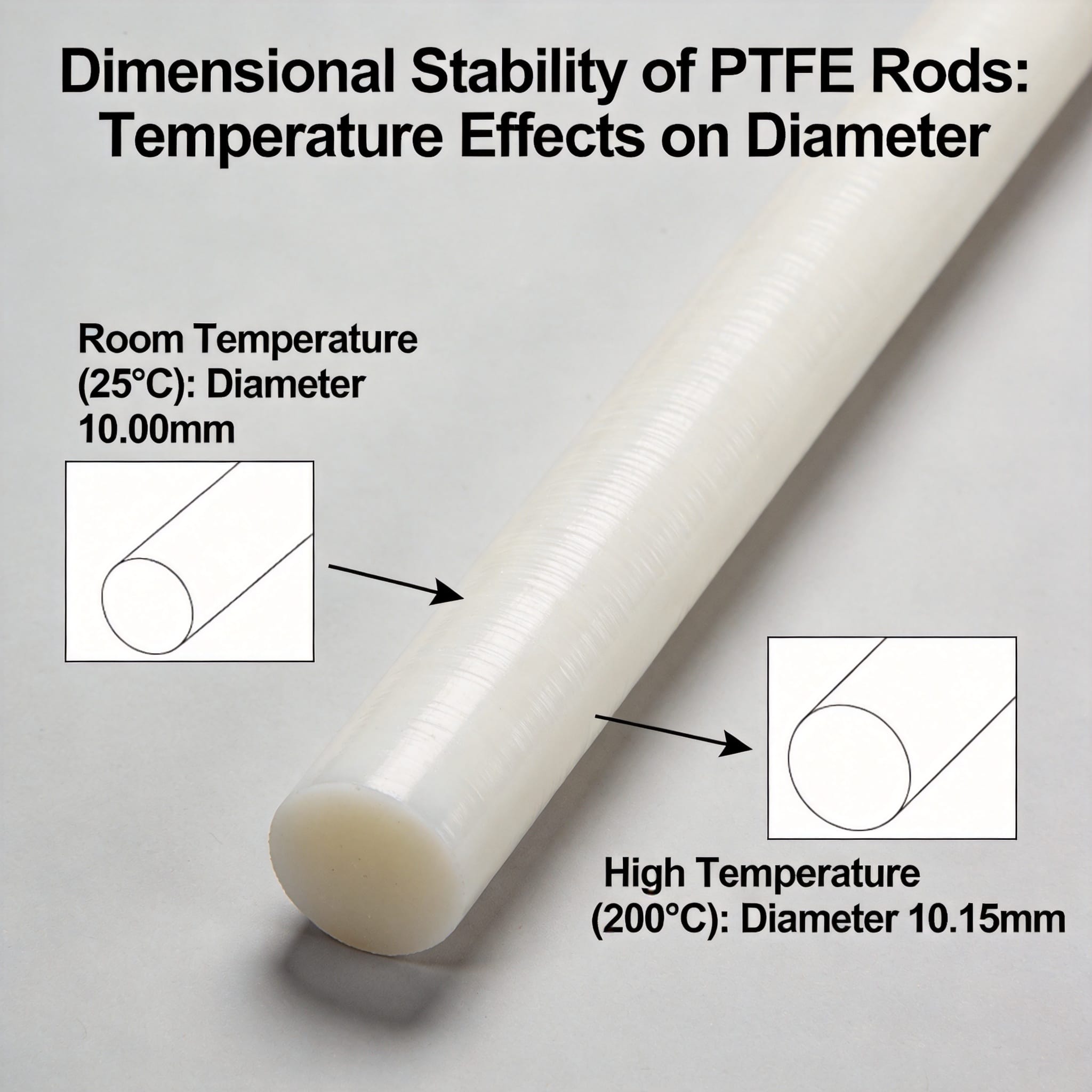
If your tolerance requires it, turn the rod on a lathe with sharp, high-positive-rake tooling, 300–600 SFM, and no coolant flooding (PTFE machines dry or with light air blast). Take 0.5 mm roughing passes and a 0.1 mm finishing pass. Re-measure after a 24-hour relaxation period — PTFE creeps, and a rod that measures 100.00 mm today may read 99.97 mm tomorrow. For complex profiles beyond simple turning, CNC machining of custom PTFE parts gives the dimensional control that hand turning cannot match.
Common Mistakes and How to Fix Them
Mistake 1 — Sizing the mold at the finished diameter
Symptom: Every rod comes out 2.5–4% undersize and the whole batch is scrapped or downgraded. Fix: Apply the shrinkage formula in Step 2 before the mold is cut. If the mold already exists, measure the actual shrinkage from one test rod and machine the cavity, or increase the finished-diameter target to compensate.
Mistake 2 — Fast decompression after pressing
Symptom: Horizontal cracks or a rough, blistered surface on the preform, often invisible until after sintering. Fix: Extend the release stroke to at least 30 seconds and hold at intermediate pressures. If cracks appear, the preform is unrecoverable — regrind is not permitted for virgin-grade certification.
Mistake 3 — Sintering too fast for the wall thickness
Symptom: A porous, chalky core with a solid skin; density measures below 2.10 g/cm³. Fix: Recalculate hold time using 1 hour per 6 mm of radius and extend the heating ramp to 40 °C/h for diameters over 80 mm. Cutting the hold time to save oven hours is the single most expensive shortcut in this process.
Mistake 4 — Measuring hot or immediately after cooling
Symptom: In-spec readings at the oven, out-of-spec readings at the customer. Fix: Let the rod stabilize at 23 ± 2 °C for 24 hours before final inspection, and record the stabilization time on the inspection sheet.
Diameter, Tolerance, and Capability Reference
Use this table as a decision rule when writing a special specification.
| Nominal Diameter | Typical As-Molded Tolerance | Shrinkage Range | Practical Note |
|---|---|---|---|
| 5–25 mm | ±0.13 mm | 2.5–3.5% | Fine-cut resin acceptable; short sintering cycle |
| 25–80 mm | ±0.25 mm | 2.8–3.8% | Granular resin; 6–10 h sinter hold |
| 80–200 mm | ±0.5% of diameter | 3.0–4.0% | Machine to tight tolerance; 10–18 h hold |
| 200–500 mm | ±0.8% of diameter | 3.2–4.2% | Press tonnage and oven height become limiting |
Two authoritative references worth keeping on hand: the ASTM D4894 standard for material requirements, and the Fluoropolymers Division of the American Chemistry Council for processing and handling guidance. For machining parameters after molding, NIST publishes polymer property data useful for tolerance budgeting.
FAQ: Custom PTFE Rod Diameters
What is the largest custom PTFE rod diameter that can be molded?
About 500 mm in practice, and the limit is equipment, not chemistry. A 500 mm rod requires roughly 7,000 cm² of press area at 25 MPa — over 1,700 tonnes of force — plus a sintering oven tall enough for the preform. Above that, manufacturers switch to isostatic molding or build the part from welded sections.
Can I get a custom diameter without paying for a new mold?
Yes, if your target is larger than a standard size. Buy the next standard diameter up and machine it down. A 110 mm standard rod can be turned to 107.5 mm, for example. This only fails when your target is smaller than the smallest standard size or when the required tolerance is tighter than as-molded capability.
How long does a custom-diameter run take?
For a 100 mm rod, plan on 30–36 hours of oven time plus 24 hours of stabilization and 1–2 days of machining. Total lead time from resin to shipped part is typically 5–8 working days, and the sintering cycle dominates — it cannot be compressed without sacrificing density.
Why does my molded rod come out oval instead of round?
Ovality above 1% almost always traces to uneven fill density or asymmetric cooling. Fix it by filling the mold in three equal increments with tamping between each, and by ensuring the rod is not sitting against a cold oven wall during the cooling ramp. Measure ovality as the difference between your largest and smallest of the twelve readings from Step 7.
Does pigmented or filled PTFE shrink differently?
Yes. Glass-filled and carbon-filled grades typically shrink 1.5–2.5% instead of 3–4%, because the filler restricts contraction. Bronze-filled grades can shrink under 1.5%. If you switch from virgin to filled resin at the same diameter, recalculate the mold cavity — reusing the virgin shrinkage factor will oversize your part. Filled rods such as customizable-size carbon-filled PTFE rod are a good example of how the filler changes both shrinkage and the achievable diameter range.

 English
 Russian
 French
 Spanish