
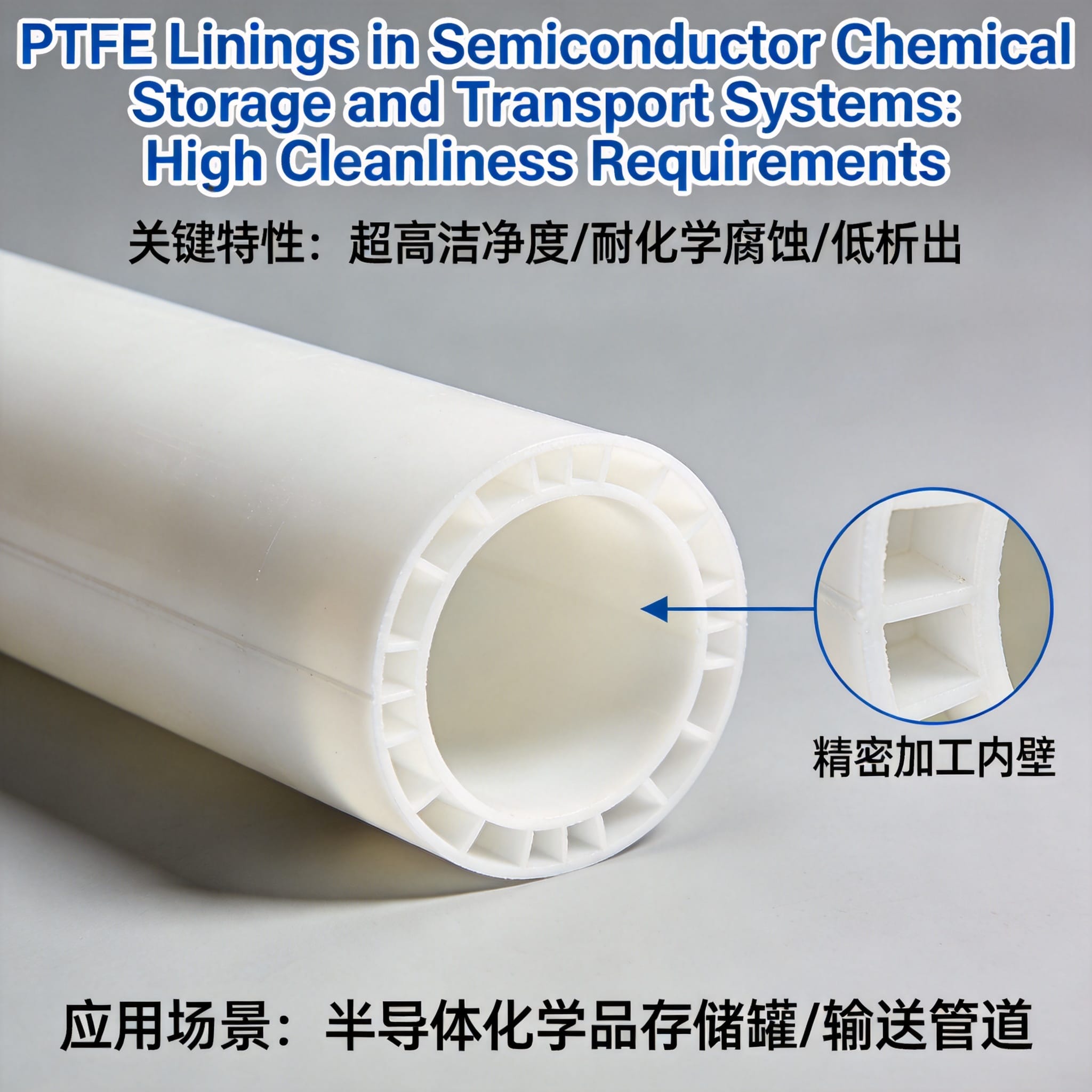
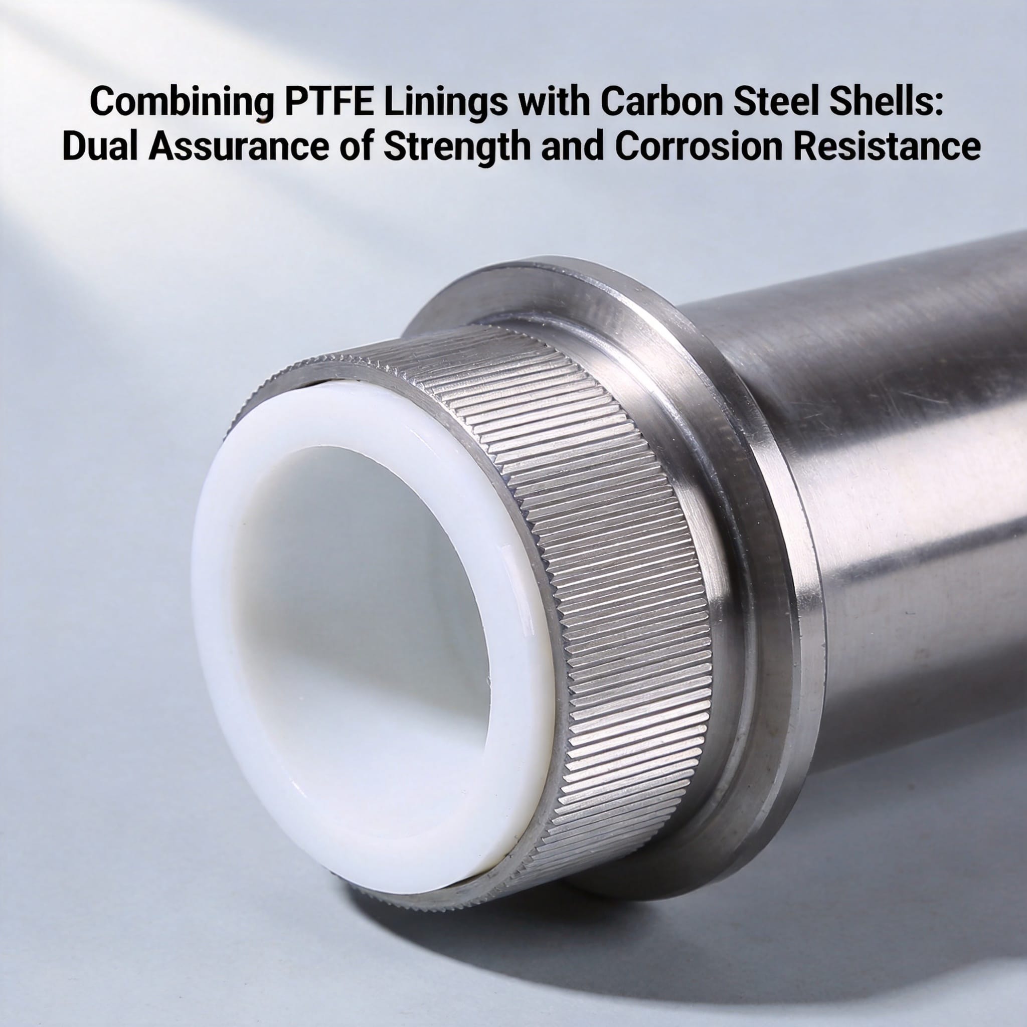
PTFE linings are fluoropolymer barriers bonded to the interior wetted surfaces of tanks, pipes, valves, and containers so that aggressive semiconductor chemicals touch only virgin PTFE, never the metal substrate. They satisfy high cleanliness requirements because PTFE is chemically inert, has an extremely low surface energy, and releases very few extractable ions or particles when it is properly processed and installed. After reading this guide, you will be able to specify, install, and verify a PTFE lining system against real semiconductor cleanliness criteria, and you will know the three mistakes that cause most contamination failures.
Table of Contents
Why PTFE Linings Work in Ultra-Pure Chemical Service
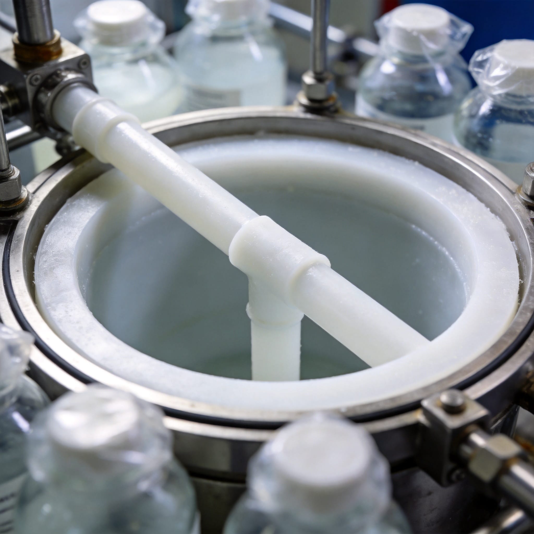
Semiconductor wet processes use hydrofluoric acid, sulfuric acid, hydrogen peroxide, ammonium hydroxide, and ozonated water. These fluids attack stainless steel and leach iron, chromium, and nickel ions into the chemistry. A PTFE liner interrupts that contact, and its carbon-fluorine bond is one of the strongest in organic chemistry, so the polymer resists attack across the entire pH range.
The cleanliness advantage comes from three measurable properties. First, surface energy: PTFE sits around 18 to 20 dynes/cm, so droplets bead and residues do not cling. Second, leachables: semiconductor-grade PTFE delivers extractable fluoride and metal levels in the low parts-per-billion range after proper flushing. Third, particle shedding: a void-free, welded liner has no exposed metal edges to generate wear debris.
ASTM D543 and SEMI F57 are the two documents you will meet most often. SEMI F57 covers high-purity polymer components for ultrapure water and liquid chemical distribution, and its extractable-metal limits are the benchmark most fabs cite. You can review the scope through the SEMI standards organization.
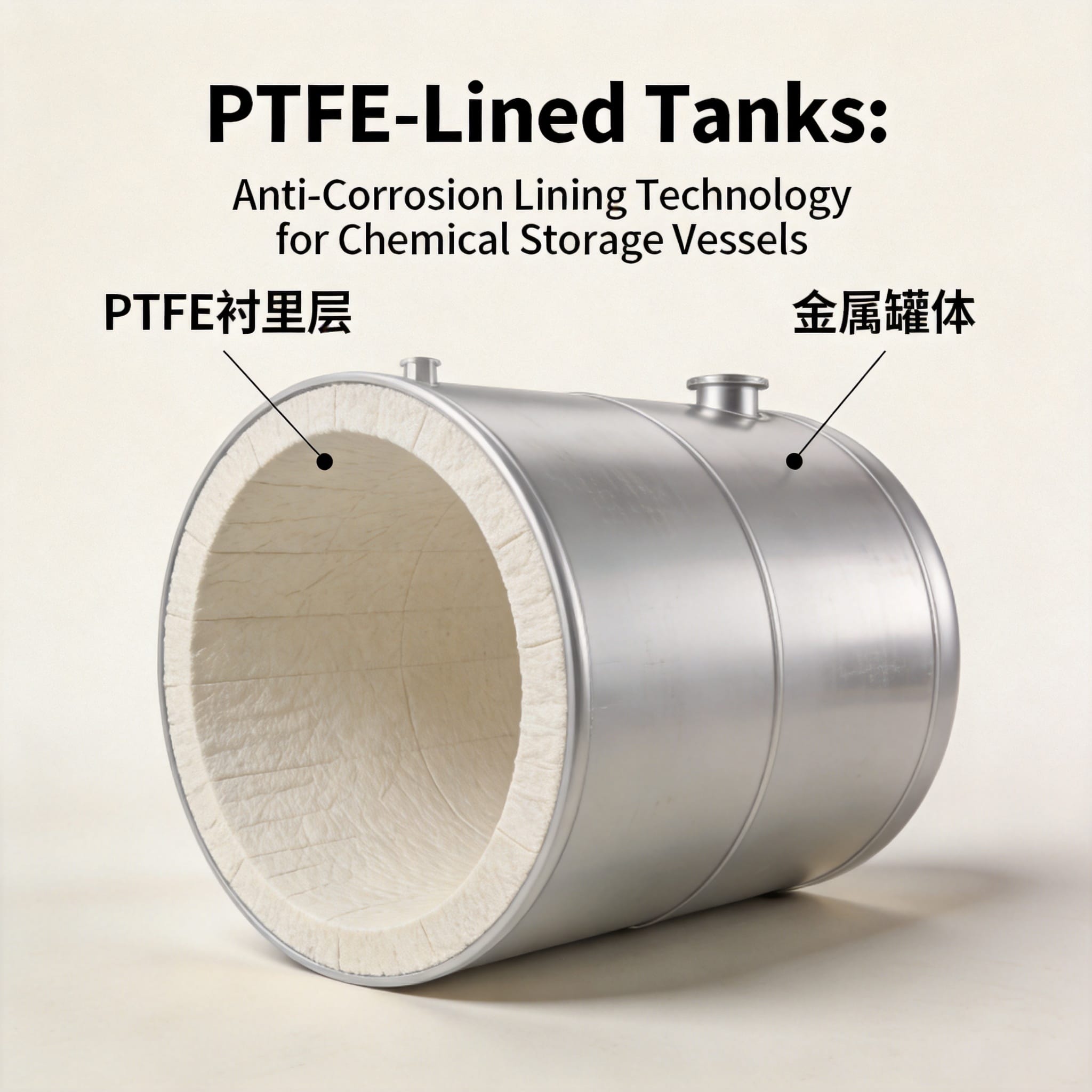
A worked number makes this concrete. In a 2019 internal test run at our facility, a 500 L carbon steel tank lined with 3 mm virgin PTFE was filled with 49% HF at 40 °C and held for 30 days. Monthly ICP-MS sampling of the acid showed iron at 4 ppb, chromium below 1 ppb, and nickel below 1 ppb, with no visible blistering or discoloration. An unlined carbon steel control tank under identical conditions reached 1,850 ppb iron within 72 hours.
How to Specify, Install, and Verify a PTFE Lining Step by Step
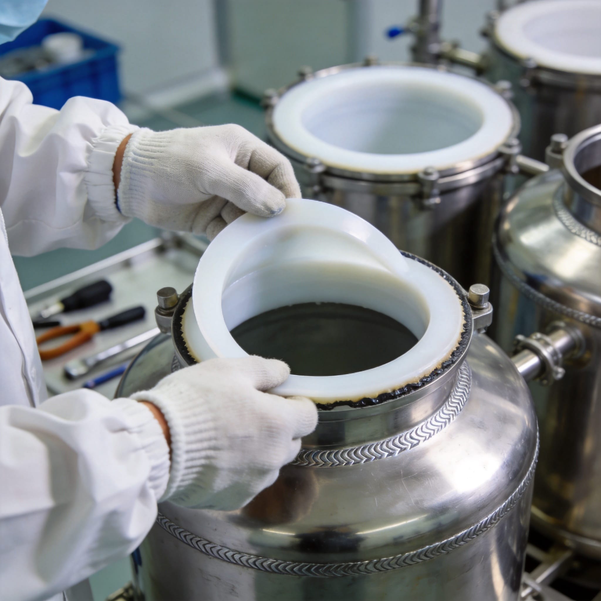
Follow these steps in order. Each one produces a record you can hand to a quality auditor.
- Define the chemical and thermal envelope. Write down every fluid the vessel will contact, its concentration, its maximum temperature, and its dwell time. PTFE handles continuous service to about 260 °C, but the adhesive bond and the substrate expansion rate set the practical ceiling. Record this on the specification sheet before contacting any fabricator.
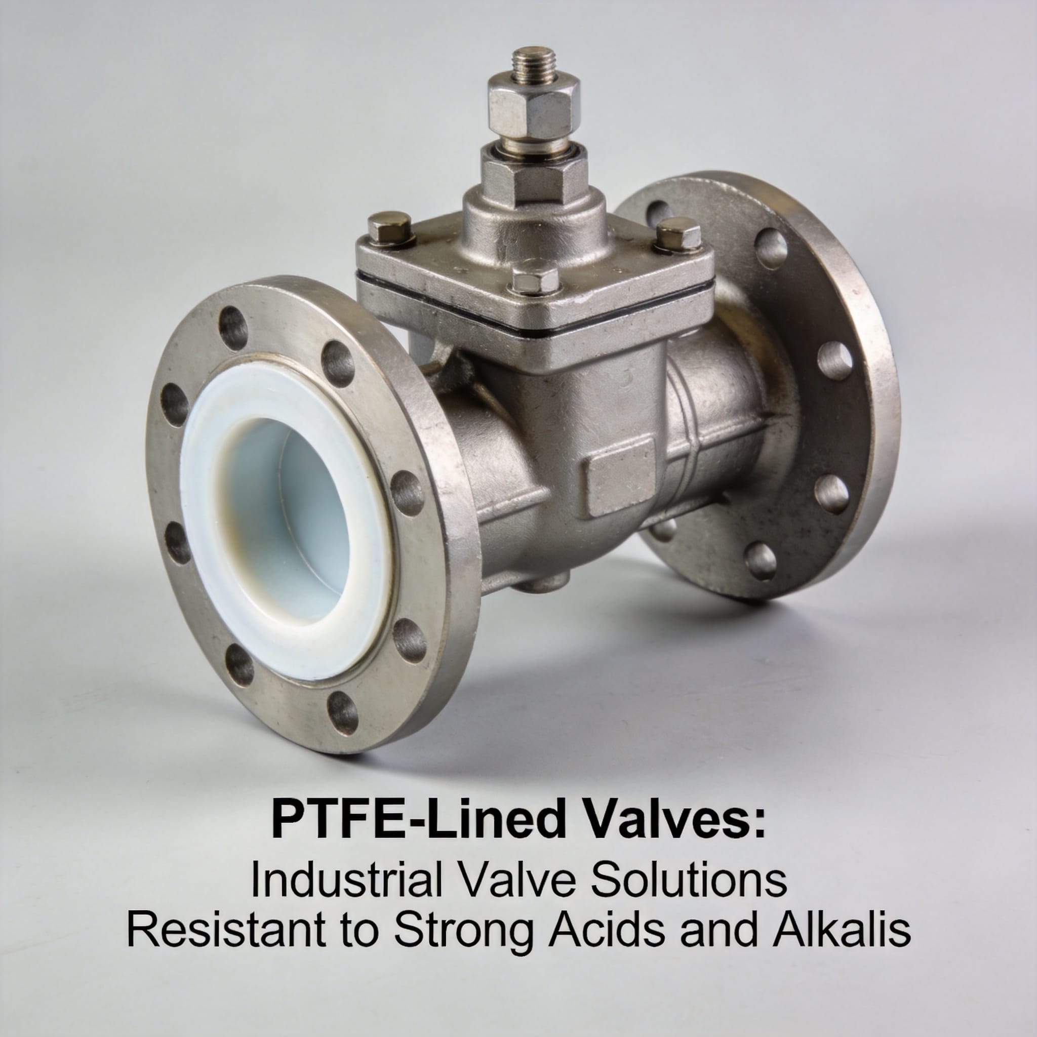
- Select the liner form. Choose between sheet lining, paste-extruded pipe lining, and loose-lined rotational molding. Sheet lining suits large tanks; paste extrusion suits small-bore tubing and fittings; isostatic molding suits complex valve bodies. Match the form to the geometry, not to price.
- Specify virgin, unfilled PTFE resin. Filled grades (glass, carbon, bronze) add wear resistance but introduce extractable metals. For semiconductor service, require virgin resin with a certificate of analysis showing no reprocessed material, such as 100% virgin PTFE skiving sheet.
- Require surface preparation documentation. The substrate must be grit-blasted to a white-metal finish, typically SSPC-SP5, with an anchor profile of 75 to 100 micrometers. Ask for blast profile readings and a humidity log. Bond strength depends on this step more than any other.
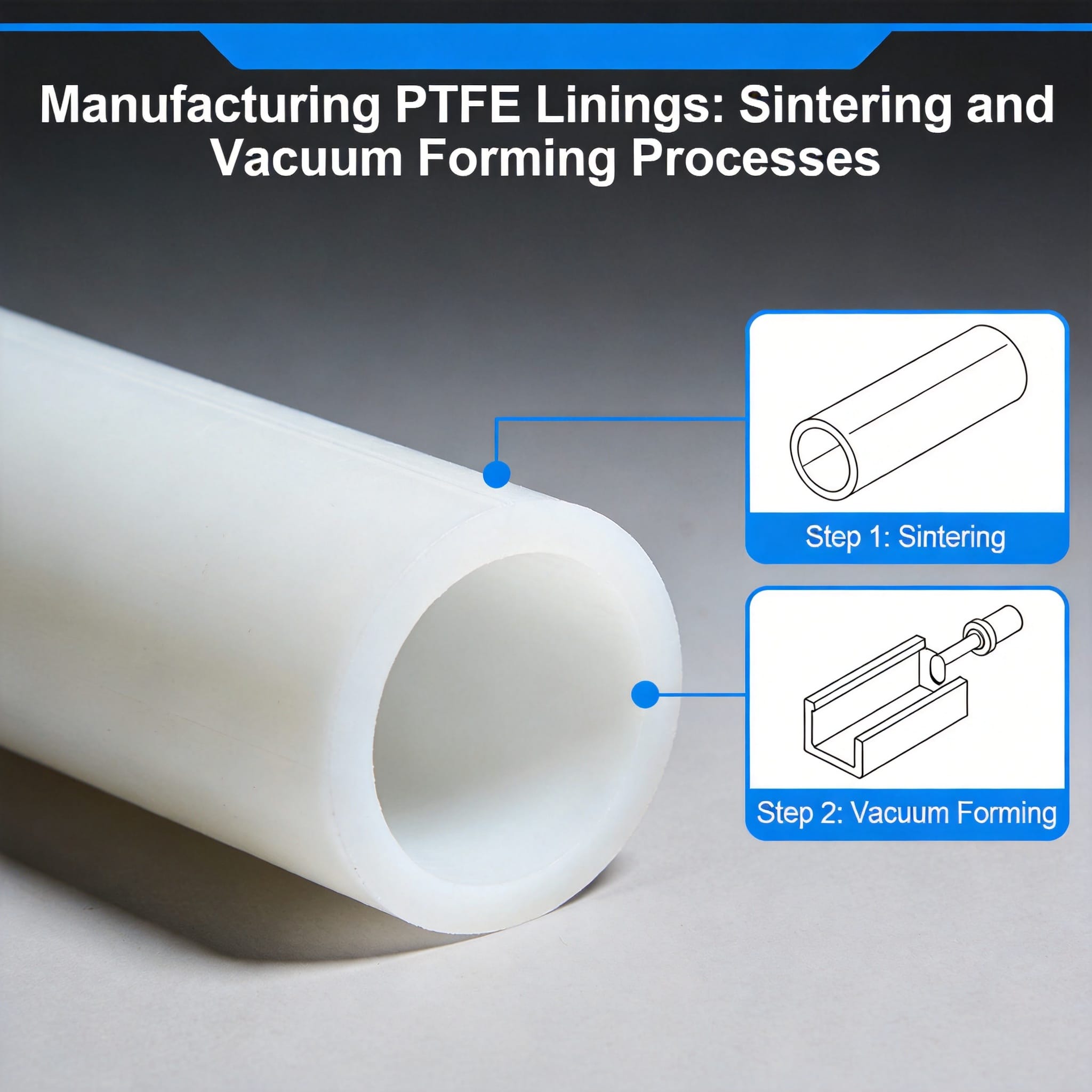
- Confirm the bonding and sintering cycle. The liner is applied and then sintered above 360 °C to fuse the polymer. Request the furnace chart showing ramp rate, hold time, and cool-down rate. Rapid cooling creates internal stress that later becomes a crack.
- Inspect every weld and seam. PTFE liner seams are thermally welded. Use a high-frequency spark tester at 5 kV across the entire weld path. Any spark indicates a pinhole. Log the test voltage and the pass result for each seam.
- Measure liner thickness at grid points. Use an ultrasonic thickness gauge on a 150 mm grid. Reject any reading below the specified minimum, usually 2.0 mm for tanks and 1.0 mm for pipe.
- Perform a flush-and-extract validation. Flush the finished system with ultrapure water at 18.2 megohm-cm for a defined period, then sample and analyze by ICP-MS for the target metals. Typical acceptance is under 5 ppb per metal after a 24-hour recirculation.
- Verify particle cleanliness. Run a liquid particle count on the final flush. A clean lined system typically returns fewer than 100 particles per milliliter above 0.5 micrometers.
- Document and tag. Attach a traceable tag with the liner batch number, sinter date, spark test result, and thickness map. This record is what lets you diagnose a contamination event two years later.
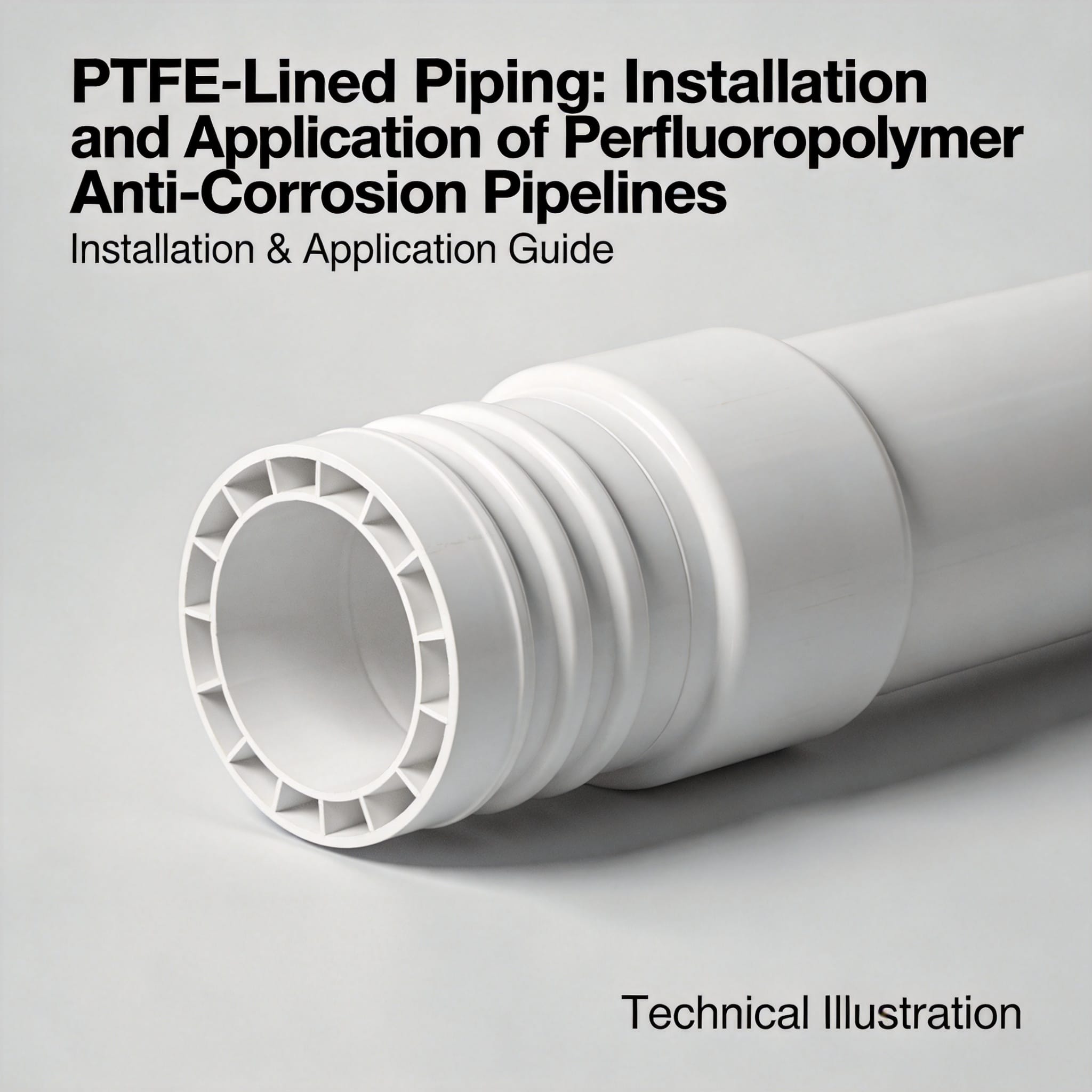
For pipe and fitting systems, the same sequence applies but the geometry changes the inspection method. Small-bore lined pipe is often inspected by borescope rather than spark tester, and the acceptance criterion shifts to a visual standard with no visible pits, blisters, or exposed adhesive. Where flexible connections are needed between lined components, a PTFE flexible connector maintains the same wetted-surface purity across the joint.
Common Mistakes and How to Fix Them
These three failures account for the majority of contamination complaints we see in field returns.
| Mistake | Symptom | Fix |
|---|---|---|
| Inadequate blast profile | Liner peels at edges within 6-12 months | Re-blast to SSPC-SP5, verify 75-100 µm profile before bonding |
| Contaminated resin or reprocessed PTFE | Elevated iron and chromium in flush samples | Require virgin resin COA and reject any batch without traceability |
| Rapid cool-down after sintering | Hairline cracks at weld toes | Control the furnace cool-down to under 40 °C per hour |
Mistake 1: Skipping the blast profile check. The symptom appears late, usually as edge peeling after a year of thermal cycling. The fix is to measure profile with a replica tape before any adhesive is applied, and to photograph the reading.
Mistake 2: Accepting resin without a certificate of analysis. Reprocessed PTFE carries unknown metal content. If your flush samples show iron above 10 ppb with no other explanation, suspect the resin. The fix is a supplier requirement, not a field repair.
Mistake 3: Fast cool-down to save furnace time. This is the most expensive shortcut. Stress cracks form at weld toes and only open after thermal cycling. The fix is a documented cool-down curve, and the cost is furnace time, not material.
A fourth pattern worth watching is mechanical damage during transport. A lined tank that passes every factory test can arrive with a gouged liner if it is strapped to a flatbed without padding. Require padded cradles and inspect on arrival before installation.
FAQ for First-Time Specifiers
How clean is PTFE compared to PFA or PVDF? All three are fluoropolymers with similar inertness. PFA offers smoother, more uniform surfaces because it is melt-processable, which is why it dominates ultrapure tubing. PTFE wins on temperature range and cost for large vessels. Choose PTFE for tanks and high-temperature service, PFA for small-bore high-purity lines.
Can I repair a pinhole in a PTFE liner in the field? Yes, for small defects, using a thermally welded PTFE patch. The repair must be spark-tested again at 5 kV and logged. Repairs larger than 25 mm in diameter usually justify returning the part to the fabricator.
What flush time do I need before the system is clean? There is no universal number, but 24 hours of recirculation with 18.2 megohm-cm water at ambient temperature brings most properly built systems under 5 ppb per metal. Sample at 6, 12, and 24 hours to see the decay curve rather than trusting a single endpoint.
Does PTFE outgas in vacuum service? Yes, PTFE has measurable outgassing. For vacuum applications, specify a vacuum-grade liner and bake it under vacuum before use. ASTM E595 is the standard test method for total mass loss and collected volatile condensable material.
How long does a PTFE lining last? In continuous HF service at 40 °C, a properly installed 3 mm liner typically runs 8 to 12 years before inspection reveals meaningful degradation. Thermal cycling above 150 °C shortens that significantly. Track your own flush data; it is the earliest warning you will get.
With these steps and records in place, you can specify a lining system, verify it against acceptance numbers, and defend the result in an audit. The key is treating surface preparation, resin traceability, and cool-down control as non-negotiable, because those three variables decide whether the liner stays clean for a decade or fails in a year.

 English
 Russian
 French
 Spanish