
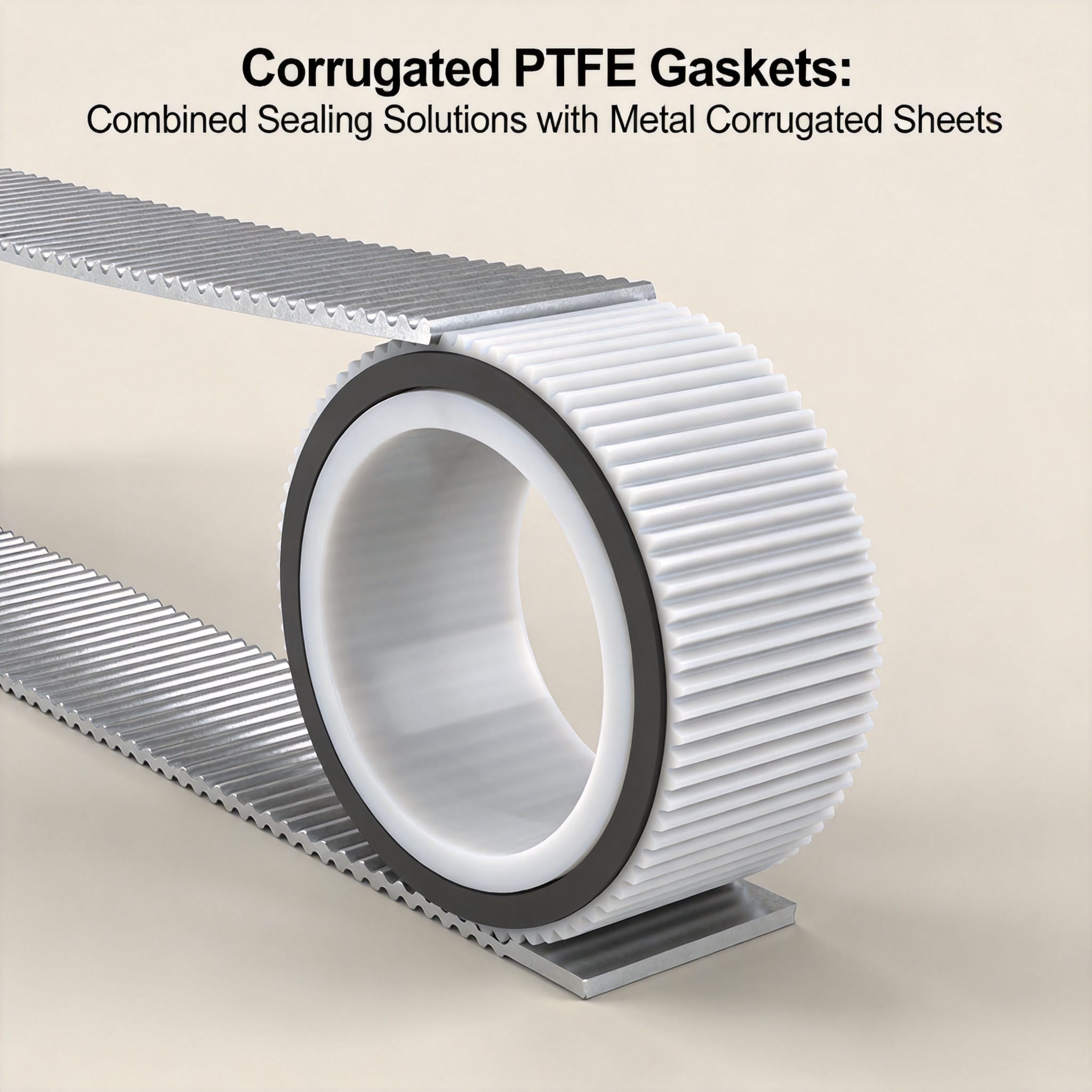
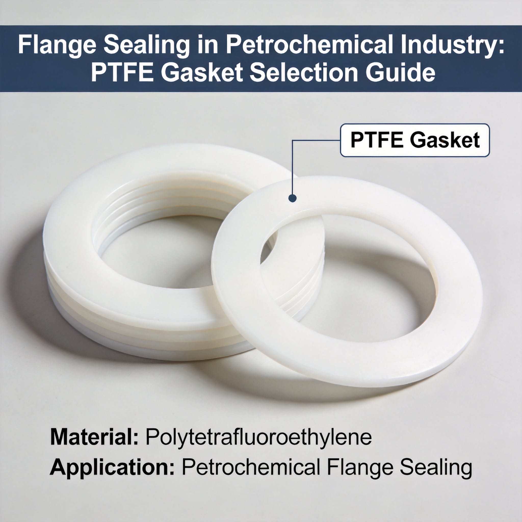
A corrugated PTFE gasket is a sealing component made by bonding (or loosely assembling) a virgin or filled PTFE facing onto a metal corrugated sheet core. The metal corrugations create concentrated sealing lines that multiply contact pressure at the flange face, while the PTFE layer provides chemical resistance and a low-friction, non-stick surface. The result is a gasket that holds high bolt load with low creep and seals aggressive media in narrow, lightweight flanges where a solid PTFE gasket would cold-flow and leak.
By the end of this article you will be able to identify when a corrugated PTFE gasket is the correct choice, install one correctly with the right bolt torque sequence, and diagnose the three most common failure modes before they cause a leak.
Table of Contents
1. Why the Corrugated PTFE + Metal Sheet Combination Works
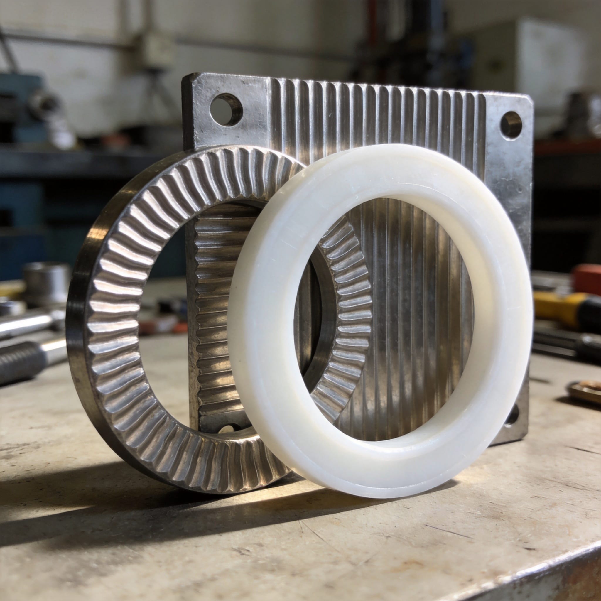
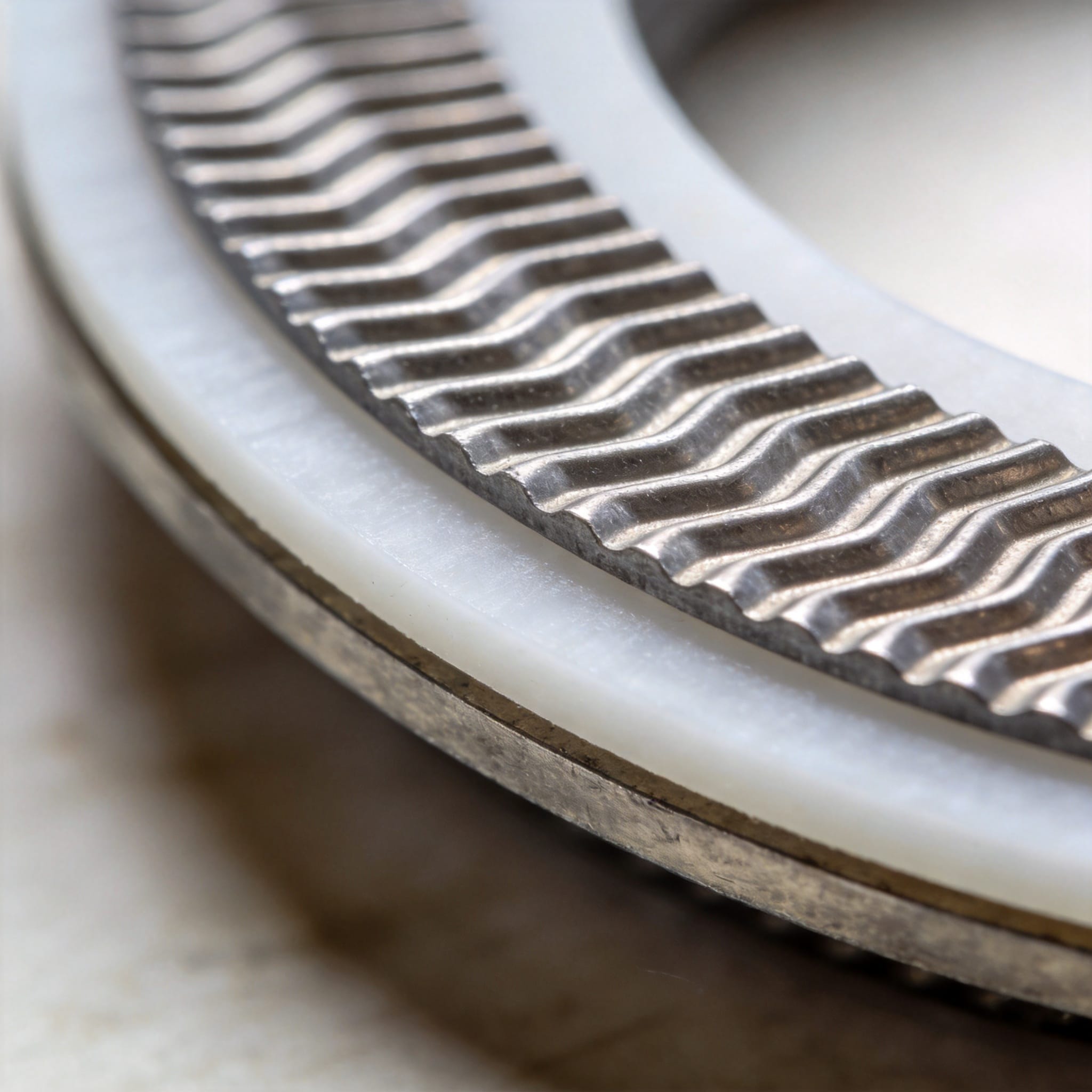
The sealing mechanism has three parts. First, the metal corrugated core acts as a spring. When you compress it, it stores elastic energy that keeps pushing back against the flange faces as the joint relaxes under thermal cycling. Second, the corrugation peaks concentrate the bolt load into narrow contact lines, so the local pressure at each peak is far higher than the average flange pressure. Third, the PTFE facing flows into the micro-roughness of the flange surface at those peaks and fills the leak path without the bulk cold-flow that destroys a plain PTFE gasket.
Compare the numbers. A plain 3 mm PTFE gasket in a 4-inch Class 150 flange typically requires 35–45 N·m per bolt to reach a usable stress, and still creeps 15–25% within 24 hours at 100 °C. A corrugated PTFE gasket of the same thickness reaches the same sealing stress at roughly 20–25 N·m because the corrugations multiply contact pressure, and creep stays under 5% because the metal core carries the load.
| Propriété | Plain PTFE gasket | Corrugated PTFE gasket |
|---|---|---|
| Bolt torque to seal | 35–45 N·m | 20–25 N·m |
| Creep after 24 h | 15–25% | < 5% |
| Recoverable spring-back | Low | High (metal core) |
| Best use case | Low-pressure, ambient | Thermal cycling, vacuum, narrow flanges |
The authoritative basis for these design rules is ASME BPVC Section VIII, Division 1, Appendix 2, which defines the gasket seating stress and the m and y factors you use to size bolt load. PTFE’s y factor is low (about 7 MPa for virgin PTFE), which is exactly why the corrugated metal core is needed to add mechanical spring-back. For the metal side of the assembly, metal corrugated gaskets for extreme pressure and temperature share the same corrugation principle and are worth comparing when the PTFE facing is not required.
2. How to Install a Corrugated PTFE Gasket (Step by Step)
Follow these steps in order. Do not skip the cleaning step; most corrugated PTFE gasket failures trace back to contaminated flange faces.
- Verify the gasket matches the flange. Check the inner diameter, outer diameter, and bolt-hole circle against the flange. A corrugated gasket must sit inside the bolt circle without covering any bolt hole.
- Clean both flange faces. Remove all old gasket residue, rust, and oil with a wire brush and solvent. Wipe dry. The faces must be bare metal with no visible film.
- Inspect for damage. Run a straight edge across each flange face. Any gap greater than 0.2 mm across the sealing area means you must resurface the flange first.
- Align the flanges. Bring the pipe ends together and insert at least half the bolts finger-tight so the gap is even all around. A misaligned flange will crush one side of the corrugations.
- Insert the gasket. Slide the corrugated PTFE gasket between the flanges. Do not bend it. If the gasket has a metal core with a locating ring, seat the ring against the bolt.
- Lubricate the bolt threads and nuts. Apply a thin, even film of molybdenum disulfide or nickel anti-seize. Dry threads need 30–40% more torque for the same load.
- Tighten in a star pattern, in three passes. Pass 1: 30% of final torque. Pass 2: 60%. Pass 3: 100%. Always move to the bolt diagonally opposite the one you just tightened.
- Re-torque after 24 hours. Thermal cycling relaxes the joint. Bring every bolt back to final torque in one star-pattern pass.
Use this torque table as a starting point, then confirm against the gasket manufacturer’s data sheet.
| Flange size | Bolt size | Class 150 | Class 300 |
|---|---|---|---|
| 1 inch | M12 | 15 N·m | 20 N·m |
| 2 inch | M16 | 25 N·m | 35 N·m |
| 4 inch | M16 | 25 N·m | 40 N·m |
| 6 inch | M20 | 45 N·m | 65 N·m |
For reference on PTFE’s chemical compatibility with your specific medium, check the Chemours Teflon technical library, which publishes compatibility charts by fluid and temperature.
3. Three Common Mistakes and How to Fix Them
Mistake 1: Over-torquing to stop a leak
Symptom: The joint leaks at low pressure, you add torque, and the leak gets worse or the gasket extrudes out of the flange gap.
Cause: Once the corrugations are flattened, the metal core can no longer spring back, and the PTFE facing is squeezed past the flange edge.
Fix: Never exceed the manufacturer’s maximum torque. If the joint still leaks at the correct torque, the flange faces are damaged or the gasket is the wrong size. Replace the gasket and resurface the flange.
Mistake 2: Reusing the gasket
Symptom: A joint that sealed perfectly for a year starts weeping after a maintenance shutdown where the gasket was reused.
Cause: The corrugations take a permanent set after the first compression. Reusing the gasket means you start with flattened peaks and zero spring-back.
Fix: Always install a new corrugated PTFE gasket. There is no safe reuse case for this design.
Mistake 3: Mixing bolt materials or skipping lubrication
Symptom: Bolts on one side of the flange are tight while the other side is still loose, and the gasket crushes unevenly.
Cause: Different friction coefficients between dry and lubricated threads, or mixing stainless and carbon steel bolts, changes the actual load for the same torque reading.
Fix: Use identical bolts throughout, lubricate all threads the same way, and tighten in the three-pass star pattern described above.
4. FAQ: Beginner Questions Answered
What temperature can a corrugated PTFE gasket handle?
Virgin PTFE facings are rated from −200 °C to +260 °C. Above 260 °C the PTFE begins to degrade. If your process runs hotter, use a filled PTFE (glass or graphite filled) facing, which extends the upper limit to about 300 °C with reduced chemical resistance. A PTFE graphite filled gasket is a common upgrade for these higher-temperature, thermally cycled joints.
Can I use a corrugated PTFE gasket on a raised-face flange?
Yes, provided the gasket outer diameter fits inside the raised face. Measure the raised-face diameter and confirm the gasket OD is at least 2 mm smaller. On a flat-face flange, the gasket must cover the full sealing area.
How do I know if my gasket has a metal corrugated core or is a spiral-wound type?
Look at the edge. A corrugated PTFE gasket shows a continuous wavy metal sheet between two PTFE layers. A spiral-wound gasket shows alternating concentric rings of metal and filler. They are not interchangeable.
What bolt load do I need for vacuum service?
Vacuum service needs the highest seating stress because the pressure differential pulls the flanges apart. Use the upper end of the torque table and re-torque after the first thermal cycle. For vacuum below 10 mbar, consult the gasket supplier’s vacuum-rated data.
Does the corrugation direction matter?
No. Corrugations run either concentrically or in a parallel pattern, and both seal the same way. What matters is that the gasket sits flat with no folds or bends before you tighten the bolts.
For a deeper background on gasket seating stress and flange design, the ASME Boiler and Pressure Vessel Code remains the primary reference used by engineers worldwide. When the application calls for a fully PTFE-facing solution instead of a metal core, a pure PTFE gasket for high-purity chemical resistant flange sealing is the natural alternative to evaluate.


 English
 Russian
 French
 Spanish