
On-site PTFE lining patching is the repair of a localized defect in a fluoropolymer lining — a blister, pinhole, scratch, or weld-line crack — by bonding a pre-formed PTFE or PFA patch directly over the damaged area without removing the equipment from service. The patch restores the chemical barrier and is typically completed in 4–8 hours from surface prep to final cure. After reading this guide, you will be able to assess whether a defect is patchable, prepare the surface, size and seal a patch, and verify the repair with a spark test.
Table of Contents
Why On-Site Patching Works
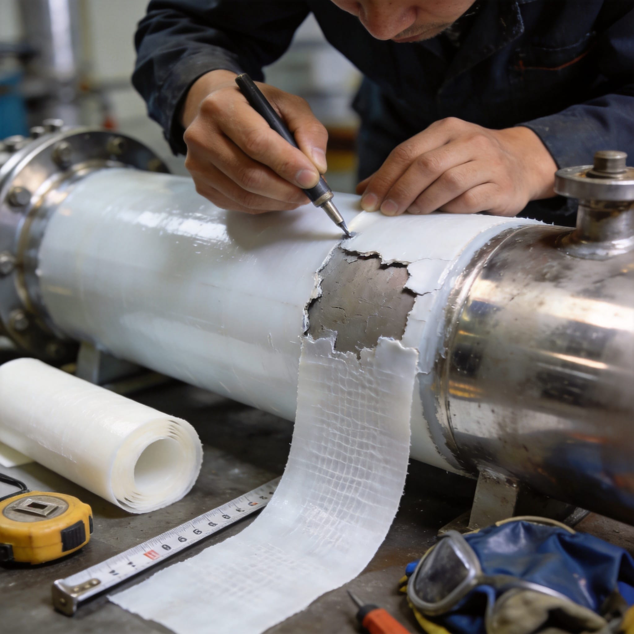
PTFE and PFA are thermoplastic fluoropolymers. Unlike thermoset rubber linings, they soften and re-fuse when heated to their melt range, which is why a patch can be welded or thermally bonded in place. PFA melts at roughly 305 °C and PTFE sinters above 340 °C, so the patch material must match the parent lining’s polymer type — a PFA patch will not fuse reliably to a PTFE sheet.
Two bonding mechanisms are used in the field. Thermal welding fuses a patch of the same polymer into the parent sheet using a hot-air or contact welder, creating a continuous, chemically identical surface. Adhesive bonding uses a fluoro-polymer adhesive film (such as FEP film) between the patch and the substrate, activated by heat and pressure. Welding is preferred for wetted, high-temperature, or aggressive chemical service; adhesive bonding is used where the lining is thin or the geometry is complex.
The repair only works if the underlying steel is intact. A patch over a corroded or blistered substrate will fail within weeks because the corrosion continues beneath it. According to NIST materials data, PTFE retains its chemical inertness across pH 0–14, but that inertness does not protect the steel behind a defect.
Patchable vs. Non-Patchable Defects
| Defect | Size / Condition | Action |
|---|---|---|
| Pinhole, scratch | < 25 mm, substrate sound | Patch on site |
| Blister | < 50 mm, no steel corrosion | Patch on site after cutting back |
| Weld-line crack | Linear, < 100 mm | Patch or re-weld |
| Blister with rust weeping | Any size | Shop re-line |
| Lining delamination | > 20% of surface | Shop re-line |
How to Patch a PTFE Lining: Step-by-Step
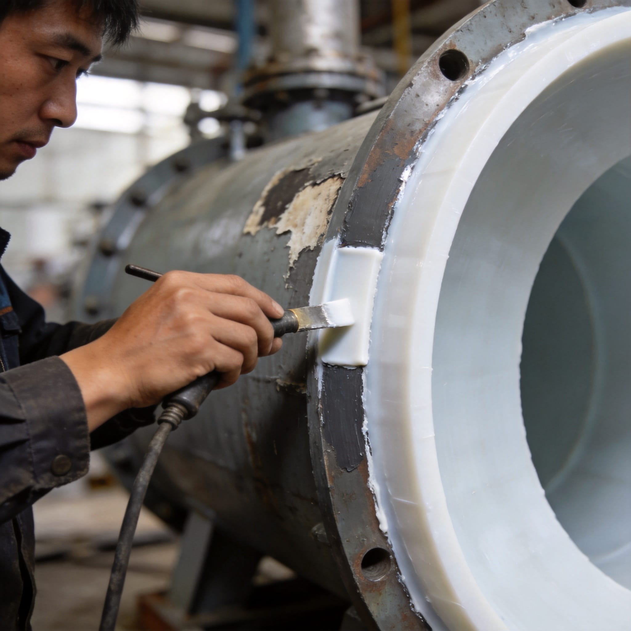
Follow these steps in order. Each step assumes the previous one is complete. Total working time is typically 4–8 hours, plus a 24-hour cure for adhesive systems.
- Isolate and drain the equipment. Close all process valves, drain the vessel, and confirm zero pressure. Vent to atmosphere.
- Test the atmosphere. Use a calibrated gas detector for the last process chemical and for oxygen. Do not enter a confined space until readings are within permit limits.
- Clean the defect area. Wipe the lining within 150 mm of the defect with a lint-free cloth and an approved solvent (typically isopropyl alcohol or acetone). Allow to flash off for 10 minutes.
- Map the defect. Trace the outer edge of the damage with a marker. Probe the edge with a blunt pick to find any hidden delamination; mark any area where the lining lifts.
- Cut back to sound lining. Using a sharp knife or rotary cutter, trim the damaged lining back to where it is fully bonded to the substrate. Remove any loose or blistered material.
- Abrasion-prep the surface. Roughen the exposed lining and a 25 mm border around it with 80–120 grit abrasive. This raises the surface energy for bonding.
- Re-clean. Wipe again with solvent and let dry. Do not touch the prepared surface with bare hands.
- Verify the substrate. Inspect the exposed steel. If you see rust, pitting, or moisture, stop — this defect needs shop re-lining.
- Cut the patch. Cut a patch of the same polymer (PTFE or PFA) at least 25 mm larger than the defect on all sides. For a 50 mm defect, the patch is 100 mm minimum. A customizable size 100% pure PTFE skived sheet is a suitable starting stock for cutting patches.
- Bevel the patch edge. Sand the patch edge to a 30–45° taper so the finished repair blends into the parent lining and does not create a stress riser.
- Position the patch. Place the patch over the defect. For adhesive bonding, insert the FEP adhesive film between patch and lining first.
- Apply heat and pressure. Using a hot-air welder set to the polymer’s weld temperature (PFA: 340–380 °C; PTFE: 380–400 °C), weld the patch perimeter in overlapping passes. Apply steady roller pressure behind the weld.
- Weld in a second direction. Cross-weld perpendicular to the first pass to eliminate pinholes at the seam.
- Cool under pressure. Hold roller pressure for 60 seconds after the last pass. Do not quench with water.
- Inspect the weld. Look for a uniform, slightly translucent bead with no gaps, charring, or bubbles.
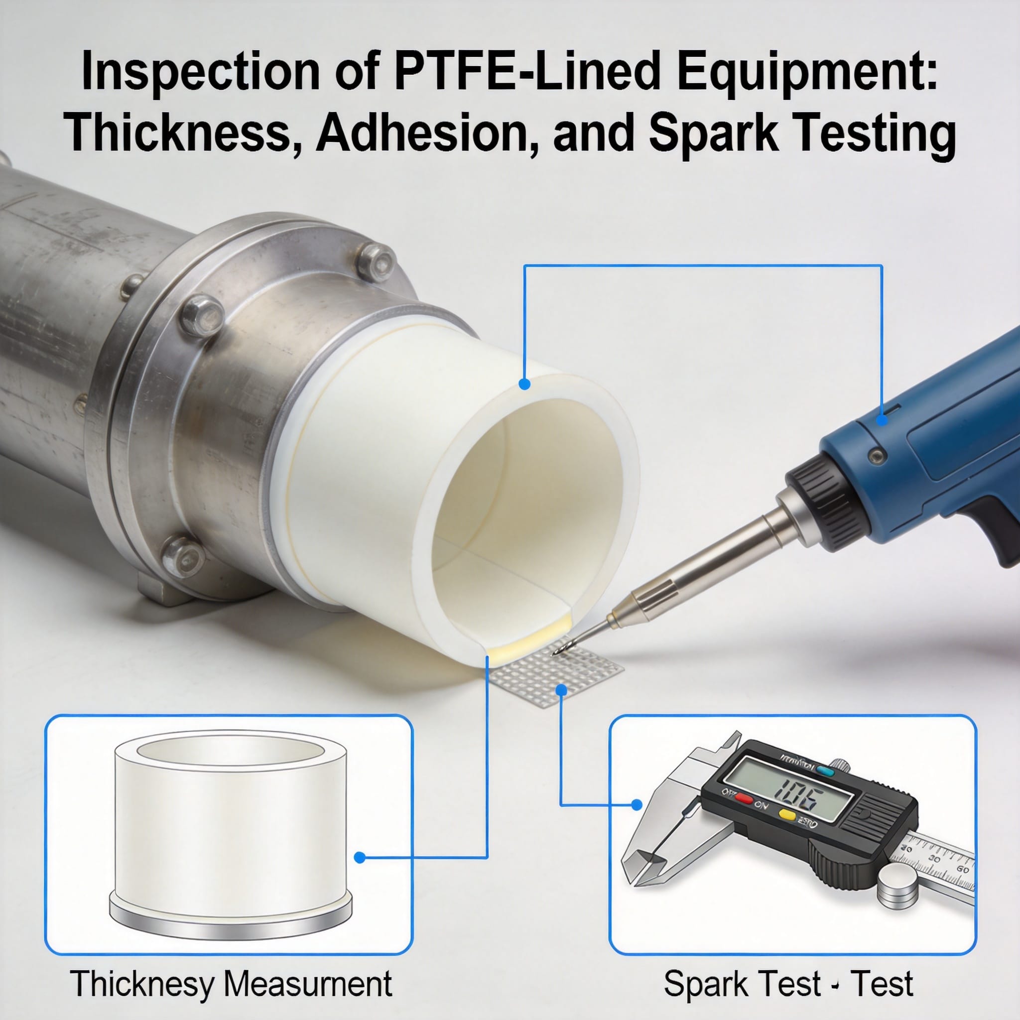
- Spark test the repair. Run a high-voltage holiday detector (typically 10–15 kV for 1–3 mm lining) across the patch and 50 mm beyond. Any spark indicates a pinhole.
- Re-test and document. If a spark appears, re-weld that spot and re-test. Record patch location, size, polymer, and test voltage.
Typical Process Parameters
| Paramètre | PFA | PTFE |
|---|---|---|
| Weld temperature | 340–380 °C | 380–400 °C |
| Patch overlap | ≥ 25 mm | ≥ 25 mm |
| Spark test voltage | 10–15 kV | 10–15 kV |
| Adhesive cure | 24 h at 25 °C | 24 h at 25 °C |
| Service temp limit | 260 °C | 260 °C |
Common Mistakes and How to Fix Them
1. Patching over an active corrosion cell
Symptom: The patch lifts within 2–6 weeks and rust stains appear at the seam. Fix: Remove the patch, cut back until you reach clean, bonded lining over sound steel, and re-patch. If the steel is pitted, the equipment must be shop re-lined.
2. Mismatched polymer
Symptom: The weld bead is dull, porous, or peels away with light finger pressure. Fix: Confirm the parent lining polymer with a burn test or the equipment datasheet before cutting the patch. PTFE and PFA do not co-weld reliably.
3. Insufficient overlap
Symptom: The patch edge curls after thermal cycling; chemical attack starts at the seam. Fix: Always maintain at least 25 mm overlap beyond the cut-back edge. For high-thermal-cycling service, use 40 mm.
4. Skipping the spark test
Symptom: A pinhole leaks weeks later, often during a production run. Fix: Never close out a patch without a holiday test at 10–15 kV. Re-weld and re-test any indicated point.
5. Wet or contaminated surface
Symptom: Bubbles or voids under the patch, visible as dark spots. Fix: Re-cut the patch, re-abrade, and re-clean with fresh solvent. Allow full flash-off before welding.
FAQ
How long does an on-site PTFE patch last?
In sound substrate conditions and correct welding, a patch typically lasts 2–5 years in moderate chemical service. In severe service — high temperature, strong acids, or frequent thermal cycling — expect 12–24 months and plan a shop re-line.
Can I patch PTFE with PFA or vice versa?
No. The two polymers have different melt ranges and do not fuse into a homogeneous seam. Always match the patch to the parent lining. If you are unsure of the parent polymer, test a small shaving with a hot soldering iron: PTFE chars and does not flow; PFA flows and turns clear.
What size defect can be patched on site?
Up to roughly 50 mm in diameter, provided the steel underneath is sound and the lining around the defect is fully bonded. Anything larger, or any defect with substrate corrosion, should go to a shop for re-lining.
Do I need a hot-air welder, or can I use a heat gun?
A heat gun cannot hold the 340–400 °C weld temperature consistently across a seam. Use a dedicated hot-air welding tool with a calibrated nozzle and a roller. This is the single biggest factor in patch reliability. For larger repairs, a high-performance PTFE skived sheet provides consistent thickness and weldability across the patch area.
How do I know the patch passed?
Two checks: a continuous, slightly translucent weld bead with no gaps or charring, and a spark test at 10–15 kV with zero indications across the patch and 50 mm beyond. Record both in the repair log. For equipment where the lining has degraded beyond patching, a fluorine-lined tank replacement may be more cost-effective than repeated field repairs.


 English
 Russian
 French
 Spanish